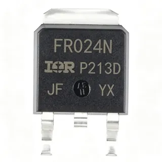
IRFR1205TRPBF - 55V N-Channel HEXFET MOSFET, 44A | Infineon
MPN: IRFR1205TRPBF ✓ פעילIRFR1205TRPBF סקירה
A power MOSFET is a voltage-controlled switch that uses an insulated gate electrode to modulate conduction between source and drain terminals. HEXFET (HEXagonal FET) is Infineon's planar-cell power-MOSFET technology that places hexagonal-shaped transistor cells across the silicon die to maximize channel width per unit area, lowering RDS(on) and improving switching efficiency. This device sits within the broader hierarchy of power MOSFETs -> power transistors -> discrete semiconductors -> active electronic components.
Key features include 27 mOhm maximum RDS(on) at VGS=10V, fast switching with low Qg/Qgd, avalanche-rated single-pulse capability, an integrated body diode for synchronous rectification, and an operating junction temperature range from -55C to +175C. The DPAK (TO-252AA) package provides a low thermal resistance of about 50 C/W junction-to-ambient when soldered to 1 oz copper, supporting sustained high-current operation without external heatsinking in moderate-duty applications.
Architecturally, the IRFR1205 uses an N-channel enhancement-mode structure: applying a positive gate-source voltage (VGS) above the threshold (~2V typical, 4V max) inverts the P-body surface into an N-channel, allowing current flow from drain to source. The fifth-generation HEXFET cell geometry shortens the channel length and improves die packing density, which is why RDS(on) per mm^2 is markedly lower than earlier generations.
Typical applications include DC-DC converters (buck, boost, synchronous rectification), low-voltage motor drivers for pumps and fans, solenoid and relay drivers, battery protection circuits in 12V/24V systems, and LED backlight driving. The 55 V rating provides comfortable margin above 24 V industrial rails and 36 V telecom buses.
Design consideration: minimize parasitic source inductance by using short, wide PCB traces and Kelvin-source layout where possible; gate-drive impedance should be kept below ~10 Ohm for clean edges. The tab is electrically tied to the drain, so PCB thermal copper must be designed with adequate clearance if the tab voltage is non-ground referenced.
This page synthesizes distributor pricing, drop-in cross-brand alternatives in the same DPAK footprint, and practical design notes not always collected in the manufacturer datasheet, delivering a single decision-ready reference for engineers.
חלופות תחליף ישיר עבור IRFR1205TRPBF — אותו מארז, תואם פין-לפין. חלקים במארז שונה הדורשים עיבוד מחדש של ה-PCB אינם נכללים.
וריאנטים בסדרה זו
דגמים מאותה סדרה התואמים Drop-in עם IRFR1205TRPBF (אותו גורם צורה וטביעת רגל) — שונים ב Technology, Drain-Source Voltage (VDS), Total Gate Charge (Qg), Drain-to-Source Voltage (VDS), Operating Temperature Range.
IRFR1205TRPBF
✅ Drop-Inצור קשר לקבלת מחיר
הצג גיליון נתונים ←IRFR5410TRPBF
✅ Drop-Inצור קשר לקבלת מחיר
הצג גיליון נתונים ←IRFR5305TRPBF
✅ Drop-Inצור קשר לקבלת מחיר
הצג גיליון נתונים ←IRFR5305TRLPBF
✅ Drop-Inצור קשר לקבלת מחיר
הצג גיליון נתונים ←NTD3055L104
✅ Drop-In📋 חלופה להתייחסות (לא בקטלוג)
RFD3055LESM9A
✅ Drop-In📋 חלופה להתייחסות (לא בקטלוג)
BSP88H6327XTSA1
✅ Drop-Inצור קשר לקבלת מחיר
הצג גיליון נתונים ←IRFR1205TRPBF דירוגים מרביים ומאפיינים חשמליים
| FET Type | N-Channel |
| Technology | HEXFET (IR MOSFET, 5th generation) |
| Drain-Source Voltage (VDS) | 55 V |
| Continuous Drain Current (ID) at TC=25C | 44 A |
| Pulsed Drain Current (IDM) | 160 A |
| Gate-Source Voltage (VGS) max | +/- 20 V |
| Gate Threshold Voltage (VGS(th)) | 2 V min, 4 V max |
| On-Resistance RDS(on) at VGS=10V | 27 mOhm max |
| Total Gate Charge (Qg) | 43.3 nC |
| Power Dissition (PD) at TC=25C | 107 W |
| טמפרטורת צומת פעולה | -55C to +175C |
| מארז | TO-252AA (DPAK) |
| סוג הרכבה | Surface Mount |
| סטטוס RoHS | Compliant (PBF suffix = lead-free) |
תצורת פינים של IRFR1205TRPBF
| פין 1 | Gate — MOSFET gate control input |
| פין 2 | Drain — Drain terminal (also electrically tied to metal tab) |
| פין 3 | Source — Source terminal (return path for gate drive) |
אזור פעולה בטוח (DC)
יישומים טיפוסיים
IRFR1205TRPBF מתאים עבור 7 יישוםs: Synchronous Rectification in DC-DC Buck Converters, 12V / 24V Brushed DC Motor Drive (Low-Side Switch), Battery Protection and Load Switch in 12-36V Systems, Solenoid and Relay Driver (PWM Control), LED Backlight Driving and High-Current LED Strings, Uninterruptible Power Supply (UPS) and Solar Charge Controllers, Automotive 12V Auxiliary Loads and Fan Control.
Synchronous Rectification in DC-DC Buck Converters
The IRFR1205TRPBF serves as the low-side synchronous rectifier in buck converters operating from 4.5V to 50V input rails. Its 27 mOhm RDS(on) at VGS=10V halves conduction loss versus a Schottky diode at currents above 5A, while the 43.3 nC total gate charge enables switching frequencies up to 500 kHz without excessive gate-drive loss. Compared to a Schottky it adds the dead-time control requirement but recovers much higher efficiency at heavy load. Use a low-side driver with adaptive dead-time to prevent shoot-through.
מומלץ
12V / 24V Brushed DC Motor Drive (Low-Side Switch)
As a low-side switch for brushed DC motors up to 30A continuous, the IRFR1205TRPBF handles 12V and 24V bus voltages comfortably within its 55V VDS rating. The 44A continuous ID rating provides a ~1.5x margin above typical motor stall currents, and the 160A pulsed rating absorbs motor-start inrush transients. Driven from a logic-level gate driver, it offers clean switching for PWM speed control. Trade-off: low-side topology floats the motor, so use an isolated gate driver if chassis grounding is required.
מומלץ
Battery Protection and Load Switch in 12-36V Systems
The IRFR1205TRPBF acts as a low-RDS(on) load switch or reverse-battery disconnect in 12V/24V/36V battery systems. With VDS rated to 55V and continuous ID up to 44A, it can switch entire battery packs without an electromechanical relay, and its body diode provides inherent free-wheeling during switch transitions. Designers use it inside BMS boards where a low-resistance disconnect is needed for short-circuit protection; pair it with a current-sense amplifier for accurate cutoff.
מומלץ
Solenoid and Relay Driver (PWM Control)
Driving solenoids, valves, and electromechanical relays at 12-24V, the IRFR1205TRPBF offers low conduction loss and 160A avalanche-rated pulse handling for flyback energy at turn-off. Adding a flyback diode reduces switching loss, but the intrinsic body diode handles brief transients if a discrete diode is omitted for BOM savings. Use a 10V gate drive to reach the datasheet's 27 mOhm RDS(on); logic-level (4.5V) drive roughly doubles RDS(on) and dissipation.
מומלץ
LED Backlight Driving and High-Current LED Strings
In high-brightness LED driving applications (automotive lighting, signage backlight), the IRFR1205TRPBF is used as a low-side linear current sink or PWM dimmer for LED strings drawing 1-30 A. Its low RDS(on) keeps dissipation manageable even at high currents - for example, 10A through 27 mOhm dissipates only 2.7W. A thermistor-controlled gate drive or current-feedback op-amp maintains LED brightness uniformity across temperature, taking advantage of the MOSFET's wide -55C to +175C junction range.
מומלץ
Uninterruptible Power Supply (UPS) and Solar Charge Controllers
Inside low-voltage UPS, solar charge controller, and battery-backup designs, the IRFR1205TRPBF handles 24V bus switching with low loss. Its 55V VDS rating tolerates 36V telecom-bus transients, and its avalanche-rated single-pulse current absorbs inductive kick from transformers during abnormal events. Compared to a relay, it switches faster (microseconds), eliminating relay-bounce and acoustic noise. Use it in combination with an MCU-controlled gate driver for soft-start to limit inrush current at power-up.
מומלץ
Automotive 12V Auxiliary Loads and Fan Control
For automotive 12V auxiliary loads such as HVAC blowers, fuel pumps, and cooling fans drawing 5-30A, the IRFR1205TRPBF provides a robust low-side switch that survives crank-start transients up to ~36V within its 55V margin. Its 160A pulsed drain current handles the inrush of motor startup, and its -55C to +175C junction range covers underhood environments. Pair with an automotive-grade gate driver (e.g. Infineon TLE4275 family) for reverse-battery and load-dump protection.
מומלץ
סיכום מוצרים מומלצים
נתוני עזר הנדסיים עבור IRFR1205TRPBF — השוואה, הנחיות תכנון ומידע על תאימות.
מדריך בחירה
השוואה עם חלופות
| פרמטר | מוצר זה | IRFR5410TRPBF | IRFR5305TRPBF | NTD3055L104 | RFD3055LESM9A | BSP88H6327XTSA1 |
|---|---|---|---|---|---|---|
| Package | TO-252AA (DPAK) | TO-252AA (DPAK) - same | TO-252AA (DPAK) - same | TO-252AA (DPAK) - same | TO-252AA (DPAK) - same | TO-252AA (DPAK) - same |
| Brand | Infineon | Infineon | Infineon | onsemi | onsemi | Infineon |
| Channel Polarity | N-Channel | N-Channel | P-Channel (opposite) | N-Channel | N-Channel | N-Channel |
| Drain-Source Voltage VDS | 55 V | 100 V | 55 V | 60 V | 60 V | 240 V |
| Continuous Drain Current ID | 44 A | 33 A | 31 A | 12 A | 10 A | 0.35 A |
| On-Resistance RDS(on) at VGS=10V | 27 mOhm max | 65 mOhm max | 65 mOhm max | 40 mOhm typ | 40 mOhm typ | 8 Ohm max |
| RoHS Compliant | Yes | Yes | Yes | Yes | Yes | Yes |
מבדילים עיקריים
- Lowest RDS(on) per mm^2 in 55V DPAK class from Infineon (לעומתIRFR5410TRPBF)
- Wide -55C to +175C junction operating range (לעומתNTD3055L104 (onsemi))
- Fifth-generation HEXFET process with optimized switching speed (לעומתBSP88H6327XTSA1 (240V Infineon part))
הערות תכנון
Estimated: at continuous 44A in free air with 1 oz copper pad (~100 mm^2 DPAK footprint), junction-to-ambient theta_JA is roughly 50-62 C/W. Power dissipation P = ID^2 * RDS(on) * Rth normalization. For a typical 12V/30A motor drive with 27 mOhm, P = 30^2 * 0.027 = 24.3 W worst-case, yielding a junction rise of 24.3 * 50 = 1215C above ambient - clearly exceeds thermal limits. Therefore: (1) drive the gate to 10V for full RDS(on) spec; (2) increase PCB copper area to at least 300 mm^2 (reduces theta_JA to ~35 C/W); (3) limit continuous current to ~15A in 50C ambient without external heatsink.
Place the gate-driver as close as possible to the gate pin to minimize parasitic inductance in the gate-source loop. Use a 10-100 Ohm gate resistor (value chosen for switching-speed vs EMI trade-off) and a 100 kohm pull-down on the gate to ensure defined off-state if the driver is tri-stated. The DPAK tab is internally tied to the drain - keep the drain copper pour on the top layer to maximize heatsinking and minimize source-loop inductance.
Critical pitfalls: (1) Driving the gate with only 4.5V (logic-level) roughly doubles RDS(on), negating the benefit of using this part over a cheaper logic-level MOSFET. (2) Exceeding the +/- 20V VGS(max) absolute rating destroys the gate oxide - verify the gate-driver supply and any transients from the gate-driver bootstrap. (3) Forgetting the body diode's reverse-recovery charge (Qrr) when designing hard-switched bridges - the IRFR1205 is best in soft-switched or low-frequency applications; at high frequencies pair with a Schottky anti-parallel diode. (4) Reverse-mounting the DPAK tab under high voltage - the tab is the drain, so PCB clearance matters.
For switching-converter applications, the IRFR1205TRPBF's 43.3 nC Qg must be supplied by the gate driver every switching cycle. At 200 kHz, average gate-drive current = Qg * fsw = 43.3 nC * 200 kHz = 8.7 mA average. Choose a gate driver capable of 1A peak (for fast rise/fall) and 10 mA average; discrete push-pull BJT/MOSFET drivers or Infineon's EiceDriver family are common picks. Dead-time in synchronous-buck topologies should be 30-100 ns to balance shoot-through risk vs body-diode conduction.
מידע על תאימות
RoHS and REACH compliant per Infineon PBF suffix. Not AEC-Q100 qualified - commercial/industrial grade. Halogen-free status not specified in verified web data.