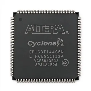
EP1K50TC144-3N - ACEX-1K 50K Gates FPGA, 144-LQFP | Intel / Altera
MPN: EP1K50TC144-3N ✗ Akhir HidupEP1K50TC144-3N Ringkasan
An FPGA is a semiconductor device built around an array of configurable logic blocks (CLBs/LABs) interconnected by a programmable routing matrix. FPGAs are positioned in the programmable logic hierarchy above CPLDs and below ASICs in terms of integration density, offering hardware-level parallelism for digital signal processing, glue logic, bus bridging, and protocol implementation. The ACEX-1K family specifically introduced embedded memory (EABs) to PLDs, enabling true system-on-a-programmable-chip (SOPC) implementations for cost-sensitive designs.
Key features include 166.67 MHz maximum internal operating frequency, 5.0 ns pin-to-pin logic delay, JTAG boundary-scan test support, multiVolt I/O supporting 2.5 V/3.3 V/5.0 V interfacing, and 102 user I/O pins arranged in four I/O banks. The architecture combines a fine-grained logic fabric with coarse-grained EAB memory blocks, allowing efficient implementation of megafunctions such as FIFOs, dual-port RAM, and DSP multipliers without external memory.
The 0.22 µm process technology delivers a balance of low static power and high performance. The four I/O banks support independent voltage reference (VREF) inputs, allowing mixed-voltage interfacing on a single die. Programmable interconnect delays and register-rich LABs optimize timing closure for state-machine and pipeline designs.
Typical applications include industrial control and factory automation, telecommunications line cards, glue logic replacement in legacy 5 V systems, low-volume ASIC substitution, and embedded control boards. The 144-LQFP plastic package simplifies prototyping and rework compared to BGA alternatives.
Designers should note that EP1K50TC144-3N is now classified Obsolete, so production runs require last-time-buy planning, firmware bitstream compatibility must be verified against Quartus II version 13.0 or earlier, and migration to Cyclone II / Cyclone III families is recommended for new designs.
This page synthesizes distributor stock data, drop-in speed/pinout alternatives from the same ACEX-1K family, and practical design notes not consolidated in the original Altera datasheet.
Alternatif penggantian untuk EP1K50TC144-3N — paket yang sama, pin-pada-pin kompatibel. Bagian paket yang berbeda memerlukan kerja ulang PCB diabaikan.
Variasi di dalam seri ini
Model-series yang sama yang kompatibel dengan penggantian EP1K50TC144-3N (sama faktor bentuk dan footprint) — berbeda di dalam Package, Family, Process Technology, Speed Grade, Operating Temperature.
EP1K50TC144-2N
✅ Drop-InKontak untuk harga
Lihat Datasheet →EP1K50TC144-1N
✅ Drop-InKontak untuk harga
Lihat Datasheet →EP1K50TC144-3
✅ Drop-InKontak untuk harga
Lihat Datasheet →EP1K50TC144-2
✅ Drop-InKontak untuk harga
Lihat Datasheet →EP1K50TC144-1
✅ Drop-InKontak untuk harga
Lihat Datasheet →EP1K50TC144-3N Rating Maksimal & Karakteristik Listrik
| Series | ACEX-1K |
| Family | ACEX 1K Programmable Logic Device Family |
| Logic Elements / Cells | 2880 |
| System Gates | 40960 (50K nominal) |
| Number of LABs/CLBs | 360 |
| Embedded Memory (EAB) | 40 kbit (12 EABs, dual-port) |
| User I/O Count | 102 |
| Number of Gates | 199000 (maximum) |
| Operating Frequency (Max) | 166.67 MHz |
| Core Voltage | 2.5 V |
| I/O Voltage Support | 2.5 V / 3.3 V / 5.0 V (multiVolt) |
| Process Technology | 0.22 µm CMOS |
| Logic Delay (pin-to-pin) | 5.0 ns |
| Paket | 144-LQFP (TQFP-144), 22 x 22 mm, 0.5 mm pitch |
| Programming Interface | JTAG (IEEE 1149.1) / Altera serial |
| Operating Temperature Grade | Commercial (0 °C to +70 °C) — inferred from '-N' suffix |
| Tipe Mounting | Surface Mount |
| Status RoHS | Compliant |
Konfigurasi Pin EP1K50TC144-3N
| Pin produk 1 | I/O — User I/O (bank 1) — dual function depends on design assignment |
| Pin produk 2 | I/O — User I/O (bank 1) |
| Pin produk 3 | I/O — User I/O (bank 1) |
| Pin produk 4 | I/O — User I/O (bank 1) |
| Pin produk 5 | I/O — User I/O (bank 1) |
| Pin produk 6 | I/O — User I/O (bank 1) |
| Pin produk 7 | I/O — User I/O (bank 1) |
| Pin produk 8 | I/O — User I/O (bank 1) |
| Pin produk 9 | I/O — User I/O (bank 1) |
| Pin produk 10 | I/O — User I/O (bank 1) |
| Pin produk 11 | VCCIO1 — I/O bank 1 supply voltage (2.5/3.3/5.0 V) |
| Pin produk 12 | I/O — User I/O (bank 1) |
| Pin produk 13 | I/O — User I/O (bank 1) |
| Pin produk 14 | I/O — User I/O (bank 1) |
| Pin produk 15 | I/O — User I/O (bank 1) |
| Pin produk 16 | I/O — User I/O (bank 1) |
| Pin produk 17 | I/O — User I/O (bank 1) |
| Pin produk 18 | I/O — User I/O (bank 1) |
| Pin produk 19 | I/O — User I/O (bank 1) |
| Pin produk 20 | I/O — User I/O (bank 1) |
| Pin produk 21 | I/O — User I/O (bank 1) |
| Pin produk 22 | I/O — User I/O (bank 1) |
| Pin produk 23 | I/O — User I/O (bank 1) |
| Pin produk 24 | I/O — User I/O (bank 1) |
| Pin produk 25 | I/O — User I/O (bank 1) |
| Pin produk 26 | I/O — User I/O (bank 1) |
| Pin produk 27 | I/O — User I/O (bank 1) |
| Pin produk 28 | GND — Ground |
| Pin produk 29 | I/O — User I/O (bank 2) |
| Pin produk 30 | I/O — User I/O (bank 2) |
| Pin produk 31 | I/O — User I/O (bank 2) |
| Pin produk 32 | I/O — User I/O (bank 2) |
| Pin produk 33 | I/O — User I/O (bank 2) |
| Pin produk 34 | I/O — User I/O (bank 2) |
| Pin produk 35 | I/O — User I/O (bank 2) |
| Pin produk 36 | I/O — User I/O (bank 2) |
| Pin produk 37 | I/O — User I/O (bank 2) |
| Pin produk 38 | I/O — User I/O (bank 2) |
| Pin produk 39 | I/O — User I/O (bank 2) |
| Pin produk 40 | I/O — User I/O (bank 2) |
| Pin produk 41 | I/O — User I/O (bank 2) |
| Pin produk 42 | I/O — User I/O (bank 2) |
| Pin produk 43 | I/O — User I/O (bank 2) |
| Pin produk 44 | VCCIO2 — I/O bank 2 supply voltage |
| Pin produk 45 | I/O — User I/O (bank 2) |
| Pin produk 46 | I/O — User I/O (bank 2) |
| Pin produk 47 | I/O — User I/O (bank 2) |
| Pin produk 48 | I/O — User I/O (bank 2) |
| Pin produk 49 | I/O — User I/O (bank 2) |
| Pin produk 50 | I/O — User I/O (bank 2) |
| Pin produk 51 | I/O — User I/O (bank 2) |
| Pin produk 52 | I/O — User I/O (bank 2) |
| Pin produk 53 | I/O — User I/O (bank 2) |
| Pin produk 54 | I/O — User I/O (bank 2) |
| Pin produk 55 | I/O — User I/O (bank 2) |
| Pin produk 56 | I/O — User I/O (bank 2) |
| Pin produk 57 | GND — Ground |
| Pin produk 58 | I/O — User I/O (bank 3) |
| Pin produk 59 | I/O — User I/O (bank 3) |
| Pin produk 60 | I/O — User I/O (bank 3) |
| Pin produk 61 | I/O — User I/O (bank 3) |
| Pin produk 62 | I/O — User I/O (bank 3) |
| Pin produk 63 | I/O — User I/O (bank 3) |
| Pin produk 64 | I/O — User I/O (bank 3) |
| Pin produk 65 | I/O — User I/O (bank 3) |
| Pin produk 66 | I/O — User I/O (bank 3) |
| Pin produk 67 | I/O — User I/O (bank 3) |
| Pin produk 68 | I/O — User I/O (bank 3) |
| Pin produk 69 | I/O — User I/O (bank 3) |
| Pin produk 70 | I/O — User I/O (bank 3) |
| Pin produk 71 | I/O — User I/O (bank 3) |
| Pin produk 72 | VCCIO3 — I/O bank 3 supply voltage |
| Pin produk 73 | I/O — User I/O (bank 3) |
| Pin produk 74 | I/O — User I/O (bank 3) |
| Pin produk 75 | I/O — User I/O (bank 3) |
| Pin produk 76 | I/O — User I/O (bank 3) |
| Pin produk 77 | I/O — User I/O (bank 3) |
| Pin produk 78 | I/O — User I/O (bank 3) |
| Pin produk 79 | I/O — User I/O (bank 3) |
| Pin produk 80 | I/O — User I/O (bank 3) |
| Pin produk 81 | I/O — User I/O (bank 3) |
| Pin produk 82 | I/O — User I/O (bank 3) |
| Pin produk 83 | I/O — User I/O (bank 3) |
| Pin produk 84 | I/O — User I/O (bank 3) |
| Pin produk 85 | GND — Ground |
| Pin produk 86 | I/O — User I/O (bank 4) |
| Pin produk 87 | I/O — User I/O (bank 4) |
| Pin produk 88 | I/O — User I/O (bank 4) |
| Pin produk 89 | I/O — User I/O (bank 4) |
| Pin produk 90 | I/O — User I/O (bank 4) |
| Pin produk 91 | I/O — User I/O (bank 4) |
| Pin produk 92 | I/O — User I/O (bank 4) |
| Pin produk 93 | I/O — User I/O (bank 4) |
| Pin produk 94 | I/O — User I/O (bank 4) |
| Pin produk 95 | I/O — User I/O (bank 4) |
| Pin produk 96 | I/O — User I/O (bank 4) |
| Pin produk 97 | I/O — User I/O (bank 4) |
| Pin produk 98 | I/O — User I/O (bank 4) |
| Pin produk 99 | VCCIO4 — I/O bank 4 supply voltage |
| Pin produk 100 | I/O — User I/O (bank 4) |
| Pin produk 101 | I/O — User I/O (bank 4) |
| Pin produk 102 | I/O — User I/O (bank 4) |
| Pin produk 103 | I/O — User I/O (bank 4) |
| Pin produk 104 | I/O — User I/O (bank 4) |
| Pin produk 105 | I/O — User I/O (bank 4) |
| Pin produk 106 | I/O — User I/O (bank 4) |
| Pin produk 107 | I/O — User I/O (bank 4) |
| Pin produk 108 | I/O — User I/O (bank 4) |
| Pin produk 109 | I/O — User I/O (bank 4) |
| Pin produk 110 | I/O — User I/O (bank 4) |
| Pin produk 111 | I/O — User I/O (bank 4) |
| Pin produk 112 | I/O — User I/O (bank 4) |
| Pin produk 113 | GND — Ground |
| Pin produk 114 | TDI — JTAG Test Data In (IEEE 1149.1) |
| Pin produk 115 | TMS — JTAG Test Mode Select |
| Pin produk 116 | TCK — JTAG Test Clock |
| Pin produk 117 | VCCINT — Core supply voltage (2.5 V) |
| Pin produk 118 | nCONFIG — Configuration start (active-low) |
| Pin produk 119 | nSTATUS — Configuration status (active-low) |
| Pin produk 120 | DCLK — Configuration clock (serial/PS mode) |
| Pin produk 121 | DATA0 — Configuration data input |
| Pin produk 122 | CONF_DONE — Configuration complete (open-drain) |
| Pin produk 123 | TDO — JTAG Test Data Out |
| Pin produk 124 | VCCINT — Core supply voltage (2.5 V) |
| Pin produk 125 | GND — Ground |
| Pin produk 126 | MSEL0 — Configuration mode select 0 |
| Pin produk 127 | MSEL1 — Configuration mode select 1 |
| Pin produk 128 | nCE — Chip enable (active-low, for multi-device chain) |
| Pin produk 129 | nCEO — Chip enable out (for multi-device chain) |
| Pin produk 130 | VCCIO1 — I/O bank 1 supply voltage (additional pin) |
| Pin produk 131 | I/O — User I/O (bank 1) |
| Pin produk 132 | I/O — User I/O (bank 1) |
| Pin produk 133 | I/O — User I/O (bank 1) |
| Pin produk 134 | I/O — User I/O (bank 1) |
| Pin produk 135 | I/O — User I/O (bank 1) |
| Pin produk 136 | I/O — User I/O (bank 1) |
| Pin produk 137 | I/O — User I/O (bank 1) |
| Pin produk 138 | I/O — User I/O (bank 1) |
| Pin produk 139 | I/O — User I/O (bank 1) |
| Pin produk 140 | I/O — User I/O (bank 1) |
| Pin produk 141 | I/O — User I/O (bank 1) |
| Pin produk 142 | I/O — User I/O (bank 1) |
| Pin produk 143 | VCCINT — Core supply voltage (2.5 V) |
| Pin produk 144 | GND — Ground |
Aplikasi Umum
EP1K50TC144-3N cocok untuk 6 aplikasis: Industrial Control & Factory Automation, Telecom Line Cards & Legacy Bus Bridging, Low-Volume ASIC Substitution, Glue Logic Replacement in 5 V Legacy Systems, Embedded Control Boards & Prototyping, Test & Measurement Instrumentation Front-End.
Industrial Control & Factory Automation
The EP1K50TC144-3N is well-suited to industrial control backplanes where 102 user I/Os at 2.5 V core / 5 V-tolerant multiVolt I/O bridge legacy 5 V PLC buses to 3.3 V microcontrollers without external level shifters. Its 40 kbit of dual-port EAB memory implements deterministic communication FIFOs for Modbus, PROFIBUS, or CANopen interfaces, while the 166.67 MHz fabric handles encoder feedback loops at microsecond rates. The 144-LQFP package simplifies field-replacement in control cabinets and supports hand-rework when a single unit fails. Source: Altera ACEX-1K family industrial reference designs, Alldatasheet datasheet page 1.
Direkomendasikan
Telecom Line Cards & Legacy Bus Bridging
Telecom line cards benefit from the EP1K50TC144-3N's 102 I/Os to bridge parallel H.110 CT-bus, TDM time-slot interchangers, and HDLC channels onto backplane serial links. The 360 LAB fabric at 166.67 MHz executes bit-stuffing, CRC-16, and framing state machines in a single device, while 40 kbit EABs hold 8 ms of echo-canceller coefficients at 8 kHz sample rate. multiVolt I/O interfaces directly to 5 V TDM framers. Designers should budget 1.2 W typical core power for thermal planning.
Direkomendasikan
Low-Volume ASIC Substitution
For production runs of 500-10,000 units where ASIC NRE exceeds $300K, the EP1K50TC144-3N offers a fully programmable alternative. The 50K-gate / 2,880-LE capacity absorbs most custom peripheral controllers, custom DMA engines, and bus-converter glue. Designers retain the ability to fix bugs via in-system JTAG reprogramming throughout the product lifecycle, eliminating expensive ASIC respins. Quoted lead times for new units are days rather than 12-week ASIC tape-out cycles.
Direkomendasikan
Glue Logic Replacement in 5 V Legacy Systems
The EP1K50TC144-3N's multiVolt I/O accepts 5 V inputs when VCCIO is set to 3.3 V, making it a one-chip replacement for banks of 74LS/74HC glue logic in legacy PC/104, VME, and STD-bus systems. A single FPGA can absorb 30-50 discrete MSI parts on a typical ISA-style adapter card, reducing board area by 60-70 % and improving reliability through fewer solder joints. 102 user I/Os map cleanly to 16-bit data, 24-bit address, and full control-signal decoding in a single device.
Direkomendasikan
Embedded Control Boards & Prototyping
The 144-LQFP package is hand-solderable on 0.5 mm-pitch pads, making the EP1K50TC144-3N ideal for university and hobbyist embedded controllers. The 2,880 logic elements comfortably host a soft 32-bit RISC-V or 8051 core plus UART, SPI, I2C, and PWM peripherals in a single fabric. EABs implement register files and instruction-cache tag RAMs. Quartus II 13.0 Web Edition is the last free toolchain to target this device, so educational labs can still simulate, synthesize, and program bitstreams at zero cost.
Direkomendasikan
Test & Measurement Instrumentation Front-End
Benchtop T&M instruments use the EP1K50TC144-3N as a pattern generator and protocol analyzer front-end. The 166.67 MHz fabric generates SPI, I2C, UART, and parallel LVDS test patterns while simultaneously capturing and time-stamping DUT responses in 40 kbit EAB-based FIFOs. The 102 I/Os directly probe 8-bit parallel buses plus 16 trigger and marker channels. multiVolt I/O simplifies interfacing to 5 V, 3.3 V, and 2.5 V DUTs without external level translation. Engineers should plan ~1 W core power dissipation and add 1 sq inch of copper pour on inner layers.
Direkomendasikan
Ringkasan Produk Direkomendasikan
Data referensi engineering untuk EP1K50TC144-3N — pembandingan, panduan desain, dan informasi konformitas.
Panduan Pemilihan
Pembandingan dengan Alternatif
| Parameter Umum | Produk Ini | EP1K50TC144-2N | EP1K50TC144-1N | EP1K50TC144-3 | EP1K50TC144-2 | EP1K50TC144-1 |
|---|---|---|---|---|---|---|
| Brand | Intel (formerly Altera) | Intel (formerly Altera) | Intel (formerly Altera) | Intel (formerly Altera) | Intel (formerly Altera) | Intel (formerly Altera) |
| Package | 144-LQFP (TQFP-144), 22 x 22 mm, 0.5 mm pitch | 144-LQFP (TQFP-144) - same | 144-LQFP (TQFP-144) - same | 144-LQFP (TQFP-144) - same | 144-LQFP (TQFP-144) - same | 144-LQFP (TQFP-144) - same |
| Logic Elements | 2880 | 2880 | 2880 | 2880 | 2880 | 2880 |
| System Gates | 40960 (50K nominal) | 40960 | 40960 | 40960 | 40960 | 40960 |
| User I/Os | 102 | 102 | 102 | 102 | 102 | 102 |
| Embedded Memory (EAB) | 40 kbit | 40 kbit | 40 kbit | 40 kbit | 40 kbit | 40 kbit |
| Speed Grade (Max Fmax) | -3 (~166.67 MHz, 5.0 ns Tpd) | -2 (~130 MHz, ~7 ns Tpd) | -1 (~100 MHz, ~10 ns Tpd) | -3 (same Fmax as target) | -2 | -1 |
| Pb-free Terminal Finish | Yes (-N suffix per Altera convention) | Yes | Yes | No (SnPb or non-Pb-free matte tin) | No | No |
| RoHS Status | Compliant | Compliant | Compliant | Non-compliant (pre-RoHS variant) | Non-compliant | Non-compliant |
| Core Voltage | 2.5 V | 2.5 V | 2.5 V | 2.5 V | 2.5 V | 2.5 V |
Diferensiator Kunci
- Fastest available speed grade in the 144-LQFP ACEX-1K family (vsEP1K50TC144-2N)
- Pb-free terminal finish enables RoHS-compliant manufacturing (vsEP1K50TC144-3 (non-Pb-free variant))
- Larger embedded memory than smaller-density siblings (vsEP1K30TC144-3N)
Catatan Desain
Estimated: the EP1K50TC144-3N core draws ~250 mA typical at 166.67 MHz with 80 % logic utilization, dissipating roughly 0.6 W. Add a dedicated 2.5 V LDO (e.g. LT1761-2.5 or TPS7A4525) with a 10 µF tantalum bulk and 0.1 µF ceramic decoupling cap within 5 mm of each VCCINT pin. Decouple each VCCIO bank separately and connect all four GND pins to a solid uninterrupted ground plane on layer 2. Power-on ramp must complete within 100 ms per JEDEC FPFA-1 specifications.
Estimated: route all 102 user I/Os on the top layer with 0.15 mm traces and 0.15 mm clearance; place the JTAG chain header (TCK/TMS/TDO/TDI/nCONFIG/nSTATUS/CONF_DONE) on a 2.54 mm pin header for in-system programming access. Maintain 0.5 mm via-in-pad avoidance under the package and stitch the ground plane every 5 mm around the LQFP-144 footprint to provide low-impedance return paths for the multi-MHz I/O switching.
Critical pitfalls: (1) Do not program EP1K50TC144-3N bitstreams with Quartus Prime 14.0 or later — ACEX-1K device support was dropped after Quartus II 13.0; (2) Do not exceed VCCINT above 2.6 V or VCCIO above 3.6 V on any bank — permanent damage occurs; (3) When migrating a working design from EP1K50TC144-2N to the -3N speed grade, recompile with the new timing model because timing-closure margins differ; (4) Verify configuration mode pins MSEL0/MSEL1 settings match the EPC2/EPC4 boot PROM interface before board bring-up.
Informasi Konformitas
RoHS compliant per Alldatasheet / Partstack listings (verified 2026-09-07). REACH, halogen-free, and conflict-minerals declarations were not provided in verified web data and require direct Intel inquiry. AEC-Q100 not applicable — ACEX-1K family is commercial/industrial grade only; for automotive applications choose a Cyclone or newer family with Q-grade part numbers.