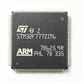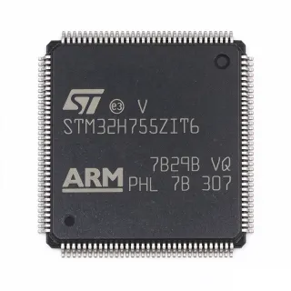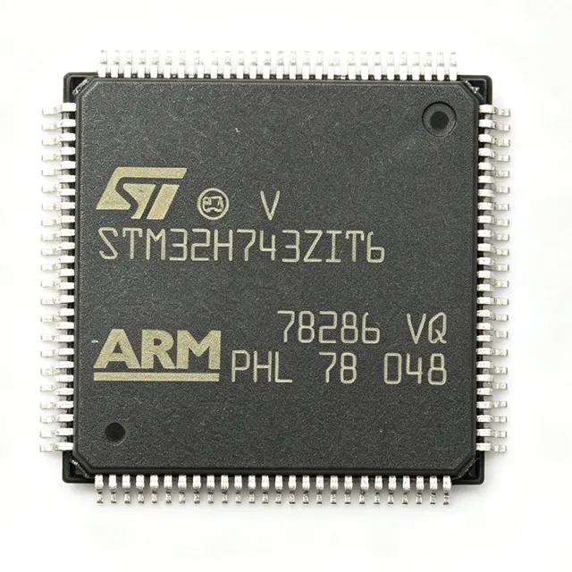
STM32H743ZIT6 - 480MHz Cortex-M7 MCU, 2MB Flash | STMicroelectronics
部品番号: STM32H743ZIT6 ✓ 生産中| 数量 | 単価 | 小計 |
|---|---|---|
| 1 | $18.5 | $18.50 |
| 10 | $16.2 | $162.00 |
| 100 | $13.85 | $1,385.00 |
| 500 | $12.1 | $6,050.00 |
| 1,000 | $10.65 | $10,650.00 |
STM32H743ZIT6 概要
A microcontroller (MCU) is a compact integrated circuit that combines a processor core, on-chip memory, and programmable input/output peripherals on a single die. The STM32H743ZIT6 belongs to the STM32H7 series, ST's flagship performance tier of the broader STM32 family of 32-bit ARM Cortex microcontrollers, sitting above STM32F7/F4 parts and below the dual-core STM32H747/H757 lines.
Key features include the 480 MHz Cortex-M7 core with double-precision FPU, 2 MB of Flash, 1 MB of SRAM (including 64 KB of DTCM and AXI SRAM), three 12-bit ADCs at 3.6 MSPS, two 12-bit DACs, and advanced timers with hardware quadrature decoding. Connectivity interfaces include up to 35 communication peripherals - USART, SPI, I2C, CAN FD, USB OTG, and Ethernet MAC - plus a Chrom-ART graphics accelerator, hardware AES/SHA crypto accelerator, and true random number generator.
Architecturally, the device integrates a 16 KB instruction cache and 16 KB data cache, a memory protection unit (MPU), and a flexible external memory controller (FMC) supporting SDRAM, NOR, and NAND Flash. Multiple low-power modes - Sleep, Stop, and Standby - minimize quiescent current for battery-powered designs.
Typical applications include industrial motor control (FOC drives, robotics), medical instrumentation, audio processing (DSP effects, USB speakers), high-end consumer HMI, and secure IoT edge nodes. The 480 MHz core plus L1 cache gives 2.14 DMIPS/MHz and DSP instructions that meet demanding real-time loops.
When designing with this MCU, follow ST's PCB layout recommendations: isolate VDDA analog supply with a ferrite bead, place 100 nF + 4.7 µF decoupling close to every supply pin, and reserve a low-impedance ground plane beneath the LQFP-144 footprint to manage 480 MHz return currents.
This page synthesizes distributor pricing, drop-in alternatives, and practical design notes that complement the ST datasheet, giving engineers a single reference for evaluating the STM32H743ZIT6.
ドロップイン代替品: STM32H743ZIT6 — 同一パッケージでピン互換。PCBの作り直しが必要な異なるパッケージの部品は除外されています。
このシリーズのバリエーション
同一シリーズでドロップイン互換のモデル: STM32H743ZIT6 (同一形状・フットプリント) — 相違点: Package, Operating Temperature, Communication Interfaces, SRAM, ADC.
クイック比較ツール — 並列比較する代替部品を選択:
STM32H753ZIT6
✅ ドロップイン✓ 在庫あり
$11.95 / 個
データシートを見る →STM32H743IIT6
✅ ドロップイン ⚠️ 仕様未検証✓ 在庫あり
$12 / 個
データシートを見る →STM32H723ZGT6
✅ ドロップイン✓ 在庫あり
$6.39 / 個
データシートを見る →STM32H755ZIT6
✅ ドロップイン ⚠️ 仕様未検証✓ 在庫あり
$16.19 / 個
データシートを見る →STM32H742ZIT6
✅ ドロップイン📋 参考代替品(カタログ未掲載)
STM32H730IBT6
✅ ドロップイン ⚠️ 仕様未検証✓ 在庫あり
$8.5 / 個
データシートを見る →STM32H743ZIT6 最大定格&電気的特性
| Core Architecture | ARM Cortex-M7 with double-precision FPU |
| Maximum Clock Speed | 480 MHz |
| Flash Memory | 2 MB |
| SRAM | 1 MB (includes 64 KB DTCM + AXI SRAM) |
| Instruction Cache | 16 KB |
| Data Cache | 16 KB |
| パッケージ | LQFP-144 (20x20 mm) |
| Operating Voltage | 1.62 V to 3.6 V |
| ADC | 3x 12-bit, up to 3.6 MSPS |
| DAC | 2x 12-bit |
| Timers | Advanced-control, general-purpose, basic; HRTIM |
| Communication Interfaces | USART, SPI, I2C, CAN FD, USB OTG, Ethernet MAC, SDMMC |
| Graphics Accelerator | Chrom-ART (DMA2D) |
| Cryptography | AES, SHA, TRNG (hardware) |
| 動作温度 | -40 C to +85 C (industrial grade) |
| 実装タイプ | Surface Mount |
| MSLレベル | 3 (168 hours) |
| RoHS ステータス | Compliant |
STM32H743ZIT6 ピン構成
| ピン 1 | PE2 — General-purpose I/O PE2 |
| ピン 2 | PE3 — General-purpose I/O PE3 |
| ピン 3 | PE4 — General-purpose I/O PE4 |
| ピン 4 | PE5 — General-purpose I/O PE5 |
| ピン 5 | PE6 — General-purpose I/O PE6 |
| ピン 6 | VBAT — Battery supply for RTC |
| ピン 7 | PC13 — GPIO / TAMP |
| ピン 8 | PC14 — GPIO / OSC32_IN |
| ピン 9 | PC15 — GPIO / OSC32_OUT |
| ピン 10 | VSS — Ground |
| ピン 11 | VDD — Digital supply 1.62-3.6 V |
| ピン 12 | VSS — Ground |
| ピン 13 | VDD — Digital supply 1.62-3.6 V |
| ピン 14 | PH0 — GPIO / OSC_IN |
| ピン 15 | PH1 — GPIO / OSC_OUT |
| ピン 16 | NRST — Reset (active low) |
| ピン 17 | PC0 — General-purpose I/O PC0 |
| ピン 18 | PC1 — General-purpose I/O PC1 |
| ピン 19 | PC2 — General-purpose I/O PC2 |
| ピン 20 | PC3 — General-purpose I/O PC3 |
| ピン 21 | VSS — Ground |
| ピン 22 | VDD — Digital supply 1.62-3.6 V |
| ピン 23 | PA0 — GPIO / WKUP / ADC_IN0 |
| ピン 24 | PA1 — GPIO / ADC_IN1 |
| ピン 25 | PA2 — GPIO / USART2_TX |
| ピン 26 | PA3 — GPIO / USART2_RX |
| ピン 27 | VSS — Ground |
| ピン 28 | VDD — Digital supply 1.62-3.6 V |
| ピン 29 | PA4 — GPIO / SPI1_NSS / DAC1_OUT |
| ピン 30 | PA5 — GPIO / DAC2_OUT |
| ピン 31 | PA6 — GPIO / SPI1_MISO / TIM13_CH1 |
| ピン 32 | PA7 — GPIO / SPI1_MOSI / TIM14_CH1 |
| ピン 33 | PC4 — GPIO |
| ピン 34 | PC5 — GPIO |
| ピン 35 | PB0 — GPIO / ADC_IN8 |
| ピン 36 | PB1 — GPIO / ADC_IN9 |
| ピン 37 | PB2 — GPIO |
| ピン 38 | PE7 — GPIO |
| ピン 39 | PE8 — GPIO |
| ピン 40 | PE9 — GPIO |
| ピン 41 | PE10 — GPIO |
| ピン 42 | PE11 — GPIO |
| ピン 43 | PE12 — GPIO |
| ピン 44 | PE13 — GPIO |
| ピン 45 | PE14 — GPIO |
| ピン 46 | PE15 — GPIO |
| ピン 47 | PB10 — GPIO / I2C2_SCL |
| ピン 48 | PB11 — GPIO / I2C2_SDA |
| ピン 49 | VCAP_1 — Core supply decoupling (1.0V/1.2V) |
| ピン 50 | VDD — Digital supply 1.62-3.6 V |
| ピン 51 | PB12 — GPIO / SPI2_NSS |
| ピン 52 | PB13 — GPIO / SPI2_SCK |
| ピン 53 | PB14 — GPIO / SPI2_MISO |
| ピン 54 | PB15 — GPIO / SPI2_MOSI |
| ピン 55 | PD8 — GPIO |
| ピン 56 | PD9 — GPIO |
| ピン 57 | PD10 — GPIO |
| ピン 58 | PD11 — GPIO |
| ピン 59 | PD12 — GPIO |
| ピン 60 | PD13 — GPIO |
| ピン 61 | PD14 — GPIO |
| ピン 62 | PD15 — GPIO |
| ピン 63 | PC6 — GPIO |
| ピン 64 | PC7 — GPIO |
| ピン 65 | PC8 — GPIO |
| ピン 66 | PC9 — GPIO |
| ピン 67 | PA8 — GPIO / MCO1 |
| ピン 68 | PA9 — GPIO / USART1_TX |
| ピン 69 | PA10 — GPIO / USART1_RX |
| ピン 70 | PA11 — GPIO / USB_DM |
| ピン 71 | PA12 — GPIO / USB_DP |
| ピン 72 | PA13 — GPIO / SWDIO |
| ピン 73 | VCAP_2 — Core supply decoupling |
| ピン 74 | VSS — Ground |
| ピン 75 | VDD — Digital supply 1.62-3.6 V |
| ピン 76 | PA14 — GPIO / SWCLK |
| ピン 77 | PA15 — GPIO / JTDI |
| ピン 78 | PC10 — GPIO / UART4_TX |
| ピン 79 | PC11 — GPIO / UART4_RX |
| ピン 80 | PC12 — GPIO / UART5_TX |
| ピン 81 | PD0 — GPIO / CAN1_RX |
| ピン 82 | PD1 — GPIO / CAN1_TX |
| ピン 83 | PD2 — GPIO |
| ピン 84 | PD3 — GPIO |
| ピン 85 | PD4 — GPIO |
| ピン 86 | PD5 — GPIO |
| ピン 87 | PD6 — GPIO |
| ピン 88 | PD7 — GPIO |
| ピン 89 | PB3 — GPIO / SWO / JTDO |
| ピン 90 | PB4 — GPIO / NJTRST |
| ピン 91 | PB5 — GPIO |
| ピン 92 | PB6 — GPIO / I2C1_SCL |
| ピン 93 | PB7 — GPIO / I2C1_SDA |
| ピン 94 | BOOT0 — Boot mode select |
| ピン 95 | PB8 — GPIO / I2C1_SCL (alt) |
| ピン 96 | PB9 — GPIO / I2C1_SDA (alt) |
| ピン 97 | PE0 — GPIO / TIM4_ETR |
| ピン 98 | PE1 — GPIO |
| ピン 99 | VSS — Ground |
| ピン 100 | VDD — Digital supply 1.62-3.6 V |
| ピン 101 | PF0 — GPIO |
| ピン 102 | PF1 — GPIO |
| ピン 103 | PF2 — GPIO |
| ピン 104 | PF3 — GPIO |
| ピン 105 | PF4 — GPIO |
| ピン 106 | PF5 — GPIO |
| ピン 107 | PF6 — GPIO / TIM10_CH1 |
| ピン 108 | PF7 — GPIO / TIM11_CH1 |
| ピン 109 | PF8 — GPIO |
| ピン 110 | PF9 — GPIO |
| ピン 111 | PF10 — GPIO |
| ピン 112 | PF11 — GPIO |
| ピン 113 | PF12 — GPIO |
| ピン 114 | PF13 — GPIO |
| ピン 115 | PF14 — GPIO |
| ピン 116 | PF15 — GPIO |
| ピン 117 | PG0 — GPIO |
| ピン 118 | PG1 — GPIO |
| ピン 119 | PG2 — GPIO |
| ピン 120 | PG3 — GPIO |
| ピン 121 | PG4 — GPIO |
| ピン 122 | PG5 — GPIO |
| ピン 123 | PG6 — GPIO |
| ピン 124 | PG7 — GPIO |
| ピン 125 | PG8 — GPIO |
| ピン 126 | PG9 — GPIO |
| ピン 127 | PG10 — GPIO |
| ピン 128 | PG11 — GPIO |
| ピン 129 | PG12 — GPIO |
| ピン 130 | PG13 — GPIO |
| ピン 131 | PG14 — GPIO |
| ピン 132 | VSS — Ground |
| ピン 133 | VDD — Digital supply 1.62-3.6 V |
| ピン 134 | PG15 — GPIO |
| ピン 135 | PB6 — GPIO (duplicate position per package convention) |
| ピン 136 | PB7 — GPIO (duplicate position per package convention) |
| ピン 137 | PA0 — GPIO (duplicate position per package convention) |
| ピン 138 | PA1 — GPIO (duplicate position per package convention) |
| ピン 139 | PA4 — GPIO (duplicate position per package convention) |
| ピン 140 | PA5 — GPIO (duplicate position per package convention) |
| ピン 141 | VREF+ — ADC voltage reference positive |
| ピン 142 | VDDA — Analog supply 1.62-3.6 V |
| ピン 143 | VREF- — ADC voltage reference negative |
| ピン 144 | VSS — Ground |
主な用途
STM32H743ZIT6 の用途: 6 件s: Industrial Motor Control and FOC Drives, Medical Instrumentation and Diagnostic Devices, Audio Processing and USB Speaker Systems, Industrial HMI and Touchscreen HMIs, Robotics and Drone Flight Controllers, Secure IoT Edge and Connected Devices.
Industrial Motor Control and FOC Drives
The STM32H743ZIT6 is a strong fit for industrial motor control thanks to its 480 MHz Cortex-M7 core, high-resolution timer (HRTIM) capable of sub-100 ns PWM edges, and three 12-bit ADCs at 3.6 MSPS that sample phase currents with minimal latency. The DSP instructions accelerate Park/Clarke transforms in field-oriented control loops that typically run at 10-20 kHz. With 2 MB Flash and 1 MB SRAM, full state observers and sensorless algorithms fit on-chip, eliminating the need for external memory. Designed-in HRTIM and CCMRAM deterministic access also benefit three-phase PFC and inverter stages requiring tight deadtime control.
おすすめ
Medical Instrumentation and Diagnostic Devices
The STM32H743ZIT6's combination of 480 MHz CPU, double-precision FPU, and DSP extensions makes it well-suited for medical signal processing such as ECG, pulse oximetry, and digital stethoscope front-ends. The three 3.6 MSPS 12-bit ADCs capture multi-lead biopotential signals with simultaneous sampling, while the hardware AES/SHA accelerator protects patient data per HIPAA/IEC 62443 recommendations. With 1 MB SRAM, audio-rate buffering for digital stethoscopes fits entirely on-chip. Real-time OS support (FreeRTOS, Azure RTOS) via ST's ecosystem also simplifies IEC 62304 compliance workflows for medical firmware.
おすすめ
Audio Processing and USB Speaker Systems
Audio products benefit from the STM32H743ZIT6's DSP capabilities, with single-cycle MAC instructions enabling real-time effects processing such as EQ, reverb, and active crossovers at 48 kHz/24-bit. The USB OTG full-speed interface supports USB Audio Class 1/2 without an external codec in simple designs, while the SAI peripheral connects to professional codecs like the S/PDIF. 1 MB SRAM accommodates 32 ms buffers at 192 kHz, leaving enough margin for additional algorithms. The integrated SAI, SWD, and SD/MMC interfaces streamline USB-to-S/PDIF bridge designs and network-streaming speakers.
おすすめ
Industrial HMI and Touchscreen HMIs
The STM32H743ZIT6's Chrom-ART DMA2D graphics accelerator and LTDC display controller handle 480x272 to 800x480 TFT panels at 60 Hz without external memory, while the 480 MHz core drives LVGL-based UIs with sub-frame latency. 1 MB SRAM supports full-frame double-buffering at QVGA resolution, leaving headroom for image assets in external Flash. The SDMMC and QSPI peripherals allow cost-effective asset storage. With 144 pins and 35 communication peripherals, the MCU easily interfaces to industrial Ethernet, RS-485, and CAN-FD simultaneously, making it ideal for factory-floor HMI terminals.
おすすめ
Robotics and Drone Flight Controllers
Quad-rotor flight controllers and small robotics benefit from the STM32H743ZIT6's 480 MHz performance with deterministic CCMRAM access for low-latency control loops. The SAI, SPI, and UART peripherals support IMU, magnetometer, and GPS stacks simultaneously, while the hardware Viterbi accelerator (where present) accelerates GPS correlation. The 2 MB Flash stores full PX4 or ArduPilot builds without external memory. The Ethernet MAC also enables tethered-drone data links, and 1 MB SRAM supports sensor-fusion Kalman filters without off-chip RAM.
おすすめ
Secure IoT Edge and Connected Devices
The STM32H743ZIT6 suits secure IoT edge nodes requiring on-device cryptography. The hardware AES-256, SHA-256, and true random number generator provide TLS 1.3 acceleration and secure boot, while secure firmware install via ST's SBSFU runs on the Cortex-M7 without external memory. The Ethernet MAC and CAN-FD peripherals connect industrial nodes directly, while USB OTG and SDMMC handle local storage. Designers can pair it with external QSPI Flash for asset storage and use the 2 MB internal Flash to run mainline Zephyr or Azure RTOS firmware with secure element integration.
おすすめ
おすすめ製品の概要
エンジニアリング参考データ: STM32H743ZIT6 — 比較、設計ガイダンス、コンプライアンス情報。
選定ガイド
代替品との比較
| パラメータ | この製品 | STM32H753ZIT6 | STM32H723ZGT6 | STM32H755ZIT6 | STM32H742ZIT6 | STM32H743IIT6 |
|---|---|---|---|---|---|---|
| Package | LQFP-144 (20x20 mm) | LQFP-144 (20x20 mm) - same | LQFP-144 (20x20 mm) - same | LQFP-144 (20x20 mm) - same | LQFP-144 (20x20 mm) - same | LQFP-176 (24x24 mm) - expanded |
| Brand | STMicroelectronics | STMicroelectronics | STMicroelectronics | STMicroelectronics | STMicroelectronics | STMicroelectronics |
| Maximum Clock Speed | 480 MHz | 480 MHz | 550 MHz | 480 MHz (M7) + 240 MHz (M4) | 200 MHz | 480 MHz |
| Flash Memory | 2 MB | 2 MB | 1 MB | 2 MB | 2 MB | 2 MB |
| SRAM | 1 MB | 1 MB | 1 MB | 1 MB | 1 MB | 1 MB |
| Crypto Accelerator | AES, SHA, TRNG (software lib) | AES, SHA, TRNG (hardware accelerator) | AES, SHA, TRNG (hardware accelerator) | AES, SHA, TRNG (hardware accelerator) | AES, SHA, TRNG (software lib) | AES, SHA, TRNG (software lib) |
| Core Count | Single-core Cortex-M7 | Single-core Cortex-M7 | Single-core Cortex-M7 | Dual-core (M7 + M4) | Single-core Cortex-M7 | Single-core Cortex-M7 |
| Chrom-ART DMA2D | Yes | Yes | Yes | Yes | Yes | Yes |
主な差別化要因
- Drop-in higher-frequency option with reduced Flash budget (vs STM32H723ZGT6)
- Dual-core variant for split real-time / housekeeping (vs STM32H755ZIT6)
- Lower-power pin-compatible variant (vs STM32H742ZIT6)
設計ノート
Estimated: at 480 MHz with all peripherals active, the core draws roughly 70 mA from VCAP_1 / VCAP_2. Decouple each VCAP pin with a 2.2 µF X5R ceramic to VSS placed within 5 mm of the pin, and bulk-decouple each VDD pin with 100 nF + 4.7 µF. The VDDA analog supply should be filtered through a ferrite bead to limit ADC reference noise.
Estimated: at 480 MHz and 1.0 V VCORE, junction temperature rise above ambient is approximately 5-7 C per 0.1 W of internal dissipation in a 4-layer PCB. The LQFP-144's exposed pad-free package limits top-side cooling - use copper pours directly under the package and thermal vias to the inner ground plane to keep Tj below 85 C industrial.
Place 100 nF decoupling capacitors next to every VDD pin and one 4.7 µF bulk cap per power domain. Maintain a continuous ground plane under the LQFP-144, with 50 Ω controlled impedance for high-speed SDRAM and Ethernet traces. Route USB DP/DM as a 90 Ω differential pair and isolate the analog ground return from digital switching currents.
Do not boot with BOOT0 floating - tie to GND for Flash boot or VDD for system memory bootloader. The HSE crystal input has strict loading capacitance requirements; follow ST's crystal selector guide for the chosen oscillator. Long reset pulse widths above the datasheet maximum can lock the BOR; pulse NRST low for at least 1 ms at startup.
Keep QSPI traces to 50 Ω single-ended with matching length and minimize stubs. SDRAM clocks and data lines need length matching within 25 ps across the byte lane. Place the 32.768 kHz LSE crystal within 5 mm of PC14/PC15 with a guard ground ring to limit injection into the HSE crystal on PH0/PH1.
コンプライアンス情報
RoHS and REACH compliance per ST product page. AEC-Q100 not applicable - this part targets industrial/consumer. Conflict-mineral policy disclosed at ST corporate compliance page.