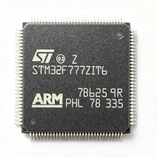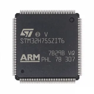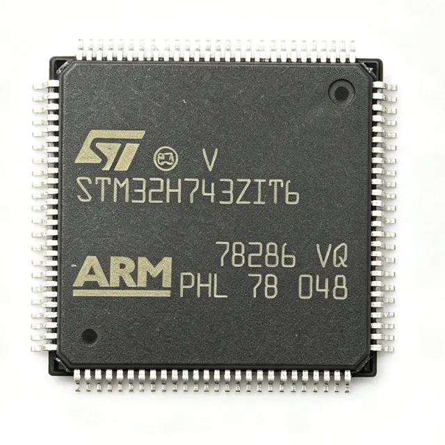
STM32H743ZIT6 - 480MHz Cortex-M7 MCU, 2MB Flash | STMicroelectronics
Référence : STM32H743ZIT6 ✓ Actif| Qté | Prix unitaire | Total |
|---|---|---|
| 1 | $18.5 | $18,50 |
| 10 | $16.2 | $162,00 |
| 100 | $13.85 | $1 385,00 |
| 500 | $12.1 | $6 050,00 |
| 1 000 | $10.65 | $10 650,00 |
STM32H743ZIT6 Présentation
A microcontroller (MCU) is a compact integrated circuit that combines a processor core, on-chip memory, and programmable input/output peripherals on a single die. The STM32H743ZIT6 belongs to the STM32H7 series, ST's flagship performance tier of the broader STM32 family of 32-bit ARM Cortex microcontrollers, sitting above STM32F7/F4 parts and below the dual-core STM32H747/H757 lines.
Key features include the 480 MHz Cortex-M7 core with double-precision FPU, 2 MB of Flash, 1 MB of SRAM (including 64 KB of DTCM and AXI SRAM), three 12-bit ADCs at 3.6 MSPS, two 12-bit DACs, and advanced timers with hardware quadrature decoding. Connectivity interfaces include up to 35 communication peripherals - USART, SPI, I2C, CAN FD, USB OTG, and Ethernet MAC - plus a Chrom-ART graphics accelerator, hardware AES/SHA crypto accelerator, and true random number generator.
Architecturally, the device integrates a 16 KB instruction cache and 16 KB data cache, a memory protection unit (MPU), and a flexible external memory controller (FMC) supporting SDRAM, NOR, and NAND Flash. Multiple low-power modes - Sleep, Stop, and Standby - minimize quiescent current for battery-powered designs.
Typical applications include industrial motor control (FOC drives, robotics), medical instrumentation, audio processing (DSP effects, USB speakers), high-end consumer HMI, and secure IoT edge nodes. The 480 MHz core plus L1 cache gives 2.14 DMIPS/MHz and DSP instructions that meet demanding real-time loops.
When designing with this MCU, follow ST's PCB layout recommendations: isolate VDDA analog supply with a ferrite bead, place 100 nF + 4.7 µF decoupling close to every supply pin, and reserve a low-impedance ground plane beneath the LQFP-144 footprint to manage 480 MHz return currents.
This page synthesizes distributor pricing, drop-in alternatives, and practical design notes that complement the ST datasheet, giving engineers a single reference for evaluating the STM32H743ZIT6.
Alternatives de remplacement direct pour STM32H743ZIT6 — même boîtier, compatible broche à broche. Les références à boîtier différent nécessitant une retouche du PCB sont exclues.
Variantes de cette série
Modèles de la même série directement compatibles avec STM32H743ZIT6 (même facteur de forme et même empreinte) — différant par Package, Operating Temperature, Communication Interfaces, SRAM, ADC.
Outil de comparaison rapide — sélectionnez des références alternatives pour une comparaison côte à côte :
STM32H753ZIT6
✅ Remplacement direct✓ En stock
$11.95 / unité
Voir la fiche technique →STM32H743IIT6
✅ Remplacement direct ⚠️ Spécifications non vérifiées✓ En stock
$12 / unité
Voir la fiche technique →STM32H723ZGT6
✅ Remplacement direct✓ En stock
$6.39 / unité
Voir la fiche technique →STM32H755ZIT6
✅ Remplacement direct ⚠️ Spécifications non vérifiées✓ En stock
$16.19 / unité
Voir la fiche technique →STM32H742ZIT6
✅ Remplacement direct📋 Alternative de référence (hors catalogue)
STM32H730IBT6
✅ Remplacement direct ⚠️ Spécifications non vérifiées✓ En stock
$8.5 / unité
Voir la fiche technique →STM32H743ZIT6 Valeurs maximales et caractéristiques électriques
| Core Architecture | ARM Cortex-M7 with double-precision FPU |
| Maximum Clock Speed | 480 MHz |
| Flash Memory | 2 MB |
| SRAM | 1 MB (includes 64 KB DTCM + AXI SRAM) |
| Instruction Cache | 16 KB |
| Data Cache | 16 KB |
| Boîtier | LQFP-144 (20x20 mm) |
| Operating Voltage | 1.62 V to 3.6 V |
| ADC | 3x 12-bit, up to 3.6 MSPS |
| DAC | 2x 12-bit |
| Timers | Advanced-control, general-purpose, basic; HRTIM |
| Communication Interfaces | USART, SPI, I2C, CAN FD, USB OTG, Ethernet MAC, SDMMC |
| Graphics Accelerator | Chrom-ART (DMA2D) |
| Cryptography | AES, SHA, TRNG (hardware) |
| Température de fonctionnement | -40 C to +85 C (industrial grade) |
| Type de montage | Surface Mount |
| Niveau MSL | 3 (168 hours) |
| Statut RoHS | Compliant |
Configuration des broches de STM32H743ZIT6
| Broche 1 | PE2 — General-purpose I/O PE2 |
| Broche 2 | PE3 — General-purpose I/O PE3 |
| Broche 3 | PE4 — General-purpose I/O PE4 |
| Broche 4 | PE5 — General-purpose I/O PE5 |
| Broche 5 | PE6 — General-purpose I/O PE6 |
| Broche 6 | VBAT — Battery supply for RTC |
| Broche 7 | PC13 — GPIO / TAMP |
| Broche 8 | PC14 — GPIO / OSC32_IN |
| Broche 9 | PC15 — GPIO / OSC32_OUT |
| Broche 10 | VSS — Ground |
| Broche 11 | VDD — Digital supply 1.62-3.6 V |
| Broche 12 | VSS — Ground |
| Broche 13 | VDD — Digital supply 1.62-3.6 V |
| Broche 14 | PH0 — GPIO / OSC_IN |
| Broche 15 | PH1 — GPIO / OSC_OUT |
| Broche 16 | NRST — Reset (active low) |
| Broche 17 | PC0 — General-purpose I/O PC0 |
| Broche 18 | PC1 — General-purpose I/O PC1 |
| Broche 19 | PC2 — General-purpose I/O PC2 |
| Broche 20 | PC3 — General-purpose I/O PC3 |
| Broche 21 | VSS — Ground |
| Broche 22 | VDD — Digital supply 1.62-3.6 V |
| Broche 23 | PA0 — GPIO / WKUP / ADC_IN0 |
| Broche 24 | PA1 — GPIO / ADC_IN1 |
| Broche 25 | PA2 — GPIO / USART2_TX |
| Broche 26 | PA3 — GPIO / USART2_RX |
| Broche 27 | VSS — Ground |
| Broche 28 | VDD — Digital supply 1.62-3.6 V |
| Broche 29 | PA4 — GPIO / SPI1_NSS / DAC1_OUT |
| Broche 30 | PA5 — GPIO / DAC2_OUT |
| Broche 31 | PA6 — GPIO / SPI1_MISO / TIM13_CH1 |
| Broche 32 | PA7 — GPIO / SPI1_MOSI / TIM14_CH1 |
| Broche 33 | PC4 — GPIO |
| Broche 34 | PC5 — GPIO |
| Broche 35 | PB0 — GPIO / ADC_IN8 |
| Broche 36 | PB1 — GPIO / ADC_IN9 |
| Broche 37 | PB2 — GPIO |
| Broche 38 | PE7 — GPIO |
| Broche 39 | PE8 — GPIO |
| Broche 40 | PE9 — GPIO |
| Broche 41 | PE10 — GPIO |
| Broche 42 | PE11 — GPIO |
| Broche 43 | PE12 — GPIO |
| Broche 44 | PE13 — GPIO |
| Broche 45 | PE14 — GPIO |
| Broche 46 | PE15 — GPIO |
| Broche 47 | PB10 — GPIO / I2C2_SCL |
| Broche 48 | PB11 — GPIO / I2C2_SDA |
| Broche 49 | VCAP_1 — Core supply decoupling (1.0V/1.2V) |
| Broche 50 | VDD — Digital supply 1.62-3.6 V |
| Broche 51 | PB12 — GPIO / SPI2_NSS |
| Broche 52 | PB13 — GPIO / SPI2_SCK |
| Broche 53 | PB14 — GPIO / SPI2_MISO |
| Broche 54 | PB15 — GPIO / SPI2_MOSI |
| Broche 55 | PD8 — GPIO |
| Broche 56 | PD9 — GPIO |
| Broche 57 | PD10 — GPIO |
| Broche 58 | PD11 — GPIO |
| Broche 59 | PD12 — GPIO |
| Broche 60 | PD13 — GPIO |
| Broche 61 | PD14 — GPIO |
| Broche 62 | PD15 — GPIO |
| Broche 63 | PC6 — GPIO |
| Broche 64 | PC7 — GPIO |
| Broche 65 | PC8 — GPIO |
| Broche 66 | PC9 — GPIO |
| Broche 67 | PA8 — GPIO / MCO1 |
| Broche 68 | PA9 — GPIO / USART1_TX |
| Broche 69 | PA10 — GPIO / USART1_RX |
| Broche 70 | PA11 — GPIO / USB_DM |
| Broche 71 | PA12 — GPIO / USB_DP |
| Broche 72 | PA13 — GPIO / SWDIO |
| Broche 73 | VCAP_2 — Core supply decoupling |
| Broche 74 | VSS — Ground |
| Broche 75 | VDD — Digital supply 1.62-3.6 V |
| Broche 76 | PA14 — GPIO / SWCLK |
| Broche 77 | PA15 — GPIO / JTDI |
| Broche 78 | PC10 — GPIO / UART4_TX |
| Broche 79 | PC11 — GPIO / UART4_RX |
| Broche 80 | PC12 — GPIO / UART5_TX |
| Broche 81 | PD0 — GPIO / CAN1_RX |
| Broche 82 | PD1 — GPIO / CAN1_TX |
| Broche 83 | PD2 — GPIO |
| Broche 84 | PD3 — GPIO |
| Broche 85 | PD4 — GPIO |
| Broche 86 | PD5 — GPIO |
| Broche 87 | PD6 — GPIO |
| Broche 88 | PD7 — GPIO |
| Broche 89 | PB3 — GPIO / SWO / JTDO |
| Broche 90 | PB4 — GPIO / NJTRST |
| Broche 91 | PB5 — GPIO |
| Broche 92 | PB6 — GPIO / I2C1_SCL |
| Broche 93 | PB7 — GPIO / I2C1_SDA |
| Broche 94 | BOOT0 — Boot mode select |
| Broche 95 | PB8 — GPIO / I2C1_SCL (alt) |
| Broche 96 | PB9 — GPIO / I2C1_SDA (alt) |
| Broche 97 | PE0 — GPIO / TIM4_ETR |
| Broche 98 | PE1 — GPIO |
| Broche 99 | VSS — Ground |
| Broche 100 | VDD — Digital supply 1.62-3.6 V |
| Broche 101 | PF0 — GPIO |
| Broche 102 | PF1 — GPIO |
| Broche 103 | PF2 — GPIO |
| Broche 104 | PF3 — GPIO |
| Broche 105 | PF4 — GPIO |
| Broche 106 | PF5 — GPIO |
| Broche 107 | PF6 — GPIO / TIM10_CH1 |
| Broche 108 | PF7 — GPIO / TIM11_CH1 |
| Broche 109 | PF8 — GPIO |
| Broche 110 | PF9 — GPIO |
| Broche 111 | PF10 — GPIO |
| Broche 112 | PF11 — GPIO |
| Broche 113 | PF12 — GPIO |
| Broche 114 | PF13 — GPIO |
| Broche 115 | PF14 — GPIO |
| Broche 116 | PF15 — GPIO |
| Broche 117 | PG0 — GPIO |
| Broche 118 | PG1 — GPIO |
| Broche 119 | PG2 — GPIO |
| Broche 120 | PG3 — GPIO |
| Broche 121 | PG4 — GPIO |
| Broche 122 | PG5 — GPIO |
| Broche 123 | PG6 — GPIO |
| Broche 124 | PG7 — GPIO |
| Broche 125 | PG8 — GPIO |
| Broche 126 | PG9 — GPIO |
| Broche 127 | PG10 — GPIO |
| Broche 128 | PG11 — GPIO |
| Broche 129 | PG12 — GPIO |
| Broche 130 | PG13 — GPIO |
| Broche 131 | PG14 — GPIO |
| Broche 132 | VSS — Ground |
| Broche 133 | VDD — Digital supply 1.62-3.6 V |
| Broche 134 | PG15 — GPIO |
| Broche 135 | PB6 — GPIO (duplicate position per package convention) |
| Broche 136 | PB7 — GPIO (duplicate position per package convention) |
| Broche 137 | PA0 — GPIO (duplicate position per package convention) |
| Broche 138 | PA1 — GPIO (duplicate position per package convention) |
| Broche 139 | PA4 — GPIO (duplicate position per package convention) |
| Broche 140 | PA5 — GPIO (duplicate position per package convention) |
| Broche 141 | VREF+ — ADC voltage reference positive |
| Broche 142 | VDDA — Analog supply 1.62-3.6 V |
| Broche 143 | VREF- — ADC voltage reference negative |
| Broche 144 | VSS — Ground |
Applications typiques
STM32H743ZIT6 convient pour 6 applications: Industrial Motor Control and FOC Drives, Medical Instrumentation and Diagnostic Devices, Audio Processing and USB Speaker Systems, Industrial HMI and Touchscreen HMIs, Robotics and Drone Flight Controllers, Secure IoT Edge and Connected Devices.
Industrial Motor Control and FOC Drives
The STM32H743ZIT6 is a strong fit for industrial motor control thanks to its 480 MHz Cortex-M7 core, high-resolution timer (HRTIM) capable of sub-100 ns PWM edges, and three 12-bit ADCs at 3.6 MSPS that sample phase currents with minimal latency. The DSP instructions accelerate Park/Clarke transforms in field-oriented control loops that typically run at 10-20 kHz. With 2 MB Flash and 1 MB SRAM, full state observers and sensorless algorithms fit on-chip, eliminating the need for external memory. Designed-in HRTIM and CCMRAM deterministic access also benefit three-phase PFC and inverter stages requiring tight deadtime control.
Recommandé
Medical Instrumentation and Diagnostic Devices
The STM32H743ZIT6's combination of 480 MHz CPU, double-precision FPU, and DSP extensions makes it well-suited for medical signal processing such as ECG, pulse oximetry, and digital stethoscope front-ends. The three 3.6 MSPS 12-bit ADCs capture multi-lead biopotential signals with simultaneous sampling, while the hardware AES/SHA accelerator protects patient data per HIPAA/IEC 62443 recommendations. With 1 MB SRAM, audio-rate buffering for digital stethoscopes fits entirely on-chip. Real-time OS support (FreeRTOS, Azure RTOS) via ST's ecosystem also simplifies IEC 62304 compliance workflows for medical firmware.
Recommandé
Audio Processing and USB Speaker Systems
Audio products benefit from the STM32H743ZIT6's DSP capabilities, with single-cycle MAC instructions enabling real-time effects processing such as EQ, reverb, and active crossovers at 48 kHz/24-bit. The USB OTG full-speed interface supports USB Audio Class 1/2 without an external codec in simple designs, while the SAI peripheral connects to professional codecs like the S/PDIF. 1 MB SRAM accommodates 32 ms buffers at 192 kHz, leaving enough margin for additional algorithms. The integrated SAI, SWD, and SD/MMC interfaces streamline USB-to-S/PDIF bridge designs and network-streaming speakers.
Recommandé
Industrial HMI and Touchscreen HMIs
The STM32H743ZIT6's Chrom-ART DMA2D graphics accelerator and LTDC display controller handle 480x272 to 800x480 TFT panels at 60 Hz without external memory, while the 480 MHz core drives LVGL-based UIs with sub-frame latency. 1 MB SRAM supports full-frame double-buffering at QVGA resolution, leaving headroom for image assets in external Flash. The SDMMC and QSPI peripherals allow cost-effective asset storage. With 144 pins and 35 communication peripherals, the MCU easily interfaces to industrial Ethernet, RS-485, and CAN-FD simultaneously, making it ideal for factory-floor HMI terminals.
Recommandé
Robotics and Drone Flight Controllers
Quad-rotor flight controllers and small robotics benefit from the STM32H743ZIT6's 480 MHz performance with deterministic CCMRAM access for low-latency control loops. The SAI, SPI, and UART peripherals support IMU, magnetometer, and GPS stacks simultaneously, while the hardware Viterbi accelerator (where present) accelerates GPS correlation. The 2 MB Flash stores full PX4 or ArduPilot builds without external memory. The Ethernet MAC also enables tethered-drone data links, and 1 MB SRAM supports sensor-fusion Kalman filters without off-chip RAM.
Recommandé
Secure IoT Edge and Connected Devices
The STM32H743ZIT6 suits secure IoT edge nodes requiring on-device cryptography. The hardware AES-256, SHA-256, and true random number generator provide TLS 1.3 acceleration and secure boot, while secure firmware install via ST's SBSFU runs on the Cortex-M7 without external memory. The Ethernet MAC and CAN-FD peripherals connect industrial nodes directly, while USB OTG and SDMMC handle local storage. Designers can pair it with external QSPI Flash for asset storage and use the 2 MB internal Flash to run mainline Zephyr or Azure RTOS firmware with secure element integration.
Recommandé
Récapitulatif des produits recommandés
Données de référence d'ingénierie pour STM32H743ZIT6 — comparaison, recommandations de conception et informations de conformité.
Guide de sélection
Comparaison avec les alternatives
| Paramètre | Ce produit | STM32H753ZIT6 | STM32H723ZGT6 | STM32H755ZIT6 | STM32H742ZIT6 | STM32H743IIT6 |
|---|---|---|---|---|---|---|
| Package | LQFP-144 (20x20 mm) | LQFP-144 (20x20 mm) - same | LQFP-144 (20x20 mm) - same | LQFP-144 (20x20 mm) - same | LQFP-144 (20x20 mm) - same | LQFP-176 (24x24 mm) - expanded |
| Brand | STMicroelectronics | STMicroelectronics | STMicroelectronics | STMicroelectronics | STMicroelectronics | STMicroelectronics |
| Maximum Clock Speed | 480 MHz | 480 MHz | 550 MHz | 480 MHz (M7) + 240 MHz (M4) | 200 MHz | 480 MHz |
| Flash Memory | 2 MB | 2 MB | 1 MB | 2 MB | 2 MB | 2 MB |
| SRAM | 1 MB | 1 MB | 1 MB | 1 MB | 1 MB | 1 MB |
| Crypto Accelerator | AES, SHA, TRNG (software lib) | AES, SHA, TRNG (hardware accelerator) | AES, SHA, TRNG (hardware accelerator) | AES, SHA, TRNG (hardware accelerator) | AES, SHA, TRNG (software lib) | AES, SHA, TRNG (software lib) |
| Core Count | Single-core Cortex-M7 | Single-core Cortex-M7 | Single-core Cortex-M7 | Dual-core (M7 + M4) | Single-core Cortex-M7 | Single-core Cortex-M7 |
| Chrom-ART DMA2D | Yes | Yes | Yes | Yes | Yes | Yes |
Principaux différenciateurs
- Drop-in higher-frequency option with reduced Flash budget (vs STM32H723ZGT6)
- Dual-core variant for split real-time / housekeeping (vs STM32H755ZIT6)
- Lower-power pin-compatible variant (vs STM32H742ZIT6)
Notes de conception
Estimated: at 480 MHz with all peripherals active, the core draws roughly 70 mA from VCAP_1 / VCAP_2. Decouple each VCAP pin with a 2.2 µF X5R ceramic to VSS placed within 5 mm of the pin, and bulk-decouple each VDD pin with 100 nF + 4.7 µF. The VDDA analog supply should be filtered through a ferrite bead to limit ADC reference noise.
Estimated: at 480 MHz and 1.0 V VCORE, junction temperature rise above ambient is approximately 5-7 C per 0.1 W of internal dissipation in a 4-layer PCB. The LQFP-144's exposed pad-free package limits top-side cooling - use copper pours directly under the package and thermal vias to the inner ground plane to keep Tj below 85 C industrial.
Place 100 nF decoupling capacitors next to every VDD pin and one 4.7 µF bulk cap per power domain. Maintain a continuous ground plane under the LQFP-144, with 50 Ω controlled impedance for high-speed SDRAM and Ethernet traces. Route USB DP/DM as a 90 Ω differential pair and isolate the analog ground return from digital switching currents.
Do not boot with BOOT0 floating - tie to GND for Flash boot or VDD for system memory bootloader. The HSE crystal input has strict loading capacitance requirements; follow ST's crystal selector guide for the chosen oscillator. Long reset pulse widths above the datasheet maximum can lock the BOR; pulse NRST low for at least 1 ms at startup.
Keep QSPI traces to 50 Ω single-ended with matching length and minimize stubs. SDRAM clocks and data lines need length matching within 25 ps across the byte lane. Place the 32.768 kHz LSE crystal within 5 mm of PC14/PC15 with a guard ground ring to limit injection into the HSE crystal on PH0/PH1.
Informations de conformité
RoHS and REACH compliance per ST product page. AEC-Q100 not applicable - this part targets industrial/consumer. Conflict-mineral policy disclosed at ST corporate compliance page.