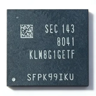
27C256A-20 - 32Kx8 CMOS EPROM 200ns | Fujitsu | Embedded Firmware
MPN: 27C256A-20 ✗ End of Life| Qty | Unit Price | Extended |
|---|---|---|
| 1 | $9.5 | $9.50 |
| 10 | $9 | $90.00 |
| 100 | $8.8 | $880.00 |
| 500 | $8.6 | $4,300.00 |
| 1,000 | $8.2 | $8,200.00 |
Drop-in alternatives for 27C256A-20 — same package, pin-to-pin compatible. Different-package parts requiring PCB rework are excluded.
Quick Comparison Tool — Select alternative parts for side-by-side comparison:
27C256A-12
✅ Drop-In ⚠️ 参数待验证✓ In Stock
$2.52 / Unit
View Datasheet →27C256A-25-X
✅ Drop-In📋 Reference alternative (not in catalog)
27C256A-12
✅ Drop-In✓ In Stock
$2.52 / Unit
View Datasheet →27C256T-15/SO
✅ Drop-In✓ In Stock
$1.9 / Unit
View Datasheet →27C256-17
✅ Drop-In✓ In Stock
Contact for price
View Datasheet →27C256-12/L
✅ Drop-In✓ In Stock
$3.9 / Unit
View Datasheet →27C256T-15/SO
✅ Drop-In✓ In Stock
$1.9 / Unit
View Datasheet →27C256A-20 Maximum Ratings & Electrical Characteristics
| Memory Size | 256 Kbit |
| Organization | 32K x 8 (32768 bytes) |
| Memory Type | OTP EPROM (CMOS) |
| Maximum Access Time | 200 ns (-20 speed grade) |
| Supply Voltage | 5 V single supply |
| Address Lines | A0 to A14 (15 lines) |
| Data Lines | O0 to O7 (8-bit, tri-state) |
| Control Signals | CE, OE, PGM |
| Standby Mode | Static standby (low-power deselect) |
| Programming Method | Fast single address location programming |
| Output Compatibility | TTL-compatible |
| Erasability | One-Time Programmable (no window) |
| Package | 28-pin DIP / PLCC (per ordering code) |
| Mounting Type | Through Hole (DIP variant) |
| Technology | CMOS |
27C256A-20 Pin Configuration
| Pin 1 | A14 — Address input, bit 14 |
| Pin 2 | A12 — Address input, bit 12 |
| Pin 3 | A7 — Address input, bit 7 |
| Pin 4 | A6 — Address input, bit 6 |
| Pin 5 | A5 — Address input, bit 5 |
| Pin 6 | A4 — Address input, bit 4 |
| Pin 7 | A3 — Address input, bit 3 |
| Pin 8 | A2 — Address input, bit 2 |
| Pin 9 | A1 — Address input, bit 1 |
| Pin 10 | A0 — Address input, bit 0 |
| Pin 11 | O0 — Data output, bit 0 (tri-state) |
| Pin 12 | O1 — Data output, bit 1 (tri-state) |
| Pin 13 | O2 — Data output, bit 2 (tri-state) |
| Pin 14 | GND — Ground reference |
| Pin 15 | O3 — Data output, bit 3 (tri-state) |
| Pin 16 | O4 — Data output, bit 4 (tri-state) |
| Pin 17 | O5 — Data output, bit 5 (tri-state) |
| Pin 18 | O6 — Data output, bit 6 (tri-state) |
| Pin 19 | O7 — Data output, bit 7 (tri-state) |
| Pin 20 | CE — Chip enable (device select) |
| Pin 21 | A10 — Address input, bit 10 |
| Pin 22 | OE — Output enable |
| Pin 23 | A11 — Address input, bit 11 |
| Pin 24 | A9 — Address input, bit 9 |
| Pin 25 | A8 — Address input, bit 8 |
| Pin 26 | A13 — Address input, bit 13 |
| Pin 27 | PGM — Program enable (programming mode) |
| Pin 28 | VCC — +5V power supply |
Safe Operating Area (SOA) & Thermal Characteristics
No official SOA curve available for this digital IC. Always operate within absolute maximum ratings specified in the datasheet. Ensure adequate cooling and derate as needed.
Typical Applications
27C256A-20 is suitable for 6 applications: Legacy Embedded Firmware Storage, Industrial Control and PLC Board Repair, Retro Computing and Arcade Board Restoration, Automotive Engine Control Unit Service, Telecom Line-Card Boot ROM, Instrumentation Firmware Upgrade and Service.
Legacy Embedded Firmware Storage
The 27C256A-20 stores boot and application firmware for 8-bit and 16-bit microcontroller systems from the 1980s-1990s era, where its 32K x 8 organization matches typical code images and its 200 ns access time meets the bus timing of MCUs such as the 8051, 68HC11, and Z180 without wait states. In this role it is placed directly on the processor memory bus with its 15 address lines and 8 tri-state data lines, controlled by CE and OE derived from the address decode logic. The static standby mode reduces board power when the code space is not being read. Because it is one-time programmable, firmware should be frozen and checksum-verified before committing to OTP parts.
Recommended
Industrial Control and PLC Board Repair
Industrial controllers, machine tools, and PLC I/O cards from the EPROM era rely on 27C256-family devices for their resident firmware, and failed or corrupted OTP devices must be replaced with pin-compatible parts to keep production lines running. The 27C256A-20's identical 28-pin JEDEC footprint and 5V TTL-compatible I/O make it a direct swap for the Fujitsu, Philips, or Microchip 27C256 originally fitted. Its 200 ns access time matches the typical timing budget of these legacy boards. Field technicians should archive the original firmware image before removal, program the replacement with a universal programmer, and verify checksums before installation.
Recommended
Retro Computing and Arcade Board Restoration
Restoration of vintage computers, game consoles, and arcade PCBs frequently requires replacing failed or previously socketed EPROMs with faithful, working equivalents. The 27C256A-20 provides the authentic 32K x 8 OTP behavior and JEDEC pinout expected by these designs, and its 200 ns access time meets the timing of 68000, Z80, and 6502-based systems used in arcade hardware. Original Fujitsu-marked devices are also valued for authenticity in concours-level restorations. Restorers typically dump the original image, verify it against known-good ROM sets, then program the replacement on a universal programmer such as the TL866 series before socketing.
Recommended
Automotive Engine Control Unit Service
Engine control units and other automotive modules from the late 1980s and 1990s used 27C256-family OTP EPROMs to hold calibration maps and firmware. Independent repair shops replacing damaged modules or performing chip-tuning need pin-compatible 32K x 8 OTP devices with reliable data retention; the 27C256A-20 provides the same 5V interface, 15-line address bus, and CE/OE control expected by these ECUs. The 200 ns access time matches the processor timing of typical era ECUs. Calibration images should be checksum-verified, and replacements should be sourced from reputable stock to avoid counterfeit devices in safety-relevant applications.
Recommended
Telecom Line-Card Boot ROM
Legacy telecom equipment such as channel banks, modems, and PBX line cards used 27C256 EPROMs for boot code and configuration constants, and carrier maintenance organizations still repair these boards to extend equipment life. The 27C256A-20's 32K x 8 organization covers typical boot images, its static standby mode limits card power draw, and the single +5V rail simplifies integration into telecom backplane designs that lack auxiliary programming voltages in operation. The 200 ns access time is compatible with the 8-bit bus controllers common in this equipment. Spares should be pre-programmed, labeled with image version, and stored with ESD precautions.
Recommended
Instrumentation Firmware Upgrade and Service
Test and measurement instruments - oscilloscopes, power supplies, and analyzers of the EPROM era - store firmware and calibration tables in 27C256 devices, and manufacturers' service centers need authentic 32K x 8 OTP parts to execute official firmware updates. The 27C256A-20 matches the original JEDEC 28-pin footprint exactly, so no PCB rework is needed, and its 200 ns timing keeps instrument processor timing unchanged. Service procedures typically require reading and archiving the current firmware (including any instrument-specific calibration constants), programming the new image with a checksum, and verifying operation before closing the unit.
Recommended
Recommended Products Summary
Engineering reference data for 27C256A-20 — comparison, design guidance, and compliance information.
Selection Guide
Comparison with Alternatives
| Parameter | This Product | 27C256A-12 | 27C256A | 27C256 |
|---|---|---|---|---|
| Package | 28-pin DIP | 28-pin DIP - same | 28-pin DIP - same | 28-pin DIP - same |
| Brand | Fujitsu | Fujitsu | NXP Semiconductors (Philips) | Microchip Technology |
| Organization | 32K x 8 | 32K x 8 | 32K x 8 | 32K x 8 |
| Access Time | 200 ns | 120 ns | [DATA_NEEDED] | [DATA_NEEDED] |
| Memory Type | CMOS OTP EPROM | CMOS OTP EPROM | CMOS EPROM | CMOS OTP EPROM |
| Supply Voltage | 5 V single supply | 5 V single supply | 5 V single supply | 5 V single supply |
| Standby Mode | Static standby | Static standby | Yes | Yes |
| Unit Price (qty 1) | $9.50 as of 2026-09-13 | [DATA_NEEDED] | [DATA_NEEDED] | [DATA_NEEDED] |
Key Differentiators
- Fastest widely available Fujitsu A-series speed grade in current surplus (vs 27C256A-25-X)
- Same-family upgrade path with faster timing (vs 27C256A-12)
- Cross-brand pin-for-pin interchangeability (vs 27C256 (Microchip Technology))
Design Notes
The 27C256A-20 is one-time programmable: a single incorrect programming voltage or over-long programming pulse permanently damages cells. Before programming, confirm the algorithm your programmer selects matches the Fujitsu 27C256A family specification, verify VPP settings, and always perform a blank check followed by a post-program verify and checksum. For development iterations, prototype with a UV-erasable 27C256 windowed device or a 28C256 EEPROM adapter rather than committing OTP parts.
The device has TTL-compatible tri-state outputs; when multiple memory devices share a data bus, ensure only one device drives the bus at a time by properly decoding CE. In legacy systems, add 0.1 uF ceramic decoupling between VCC (pin 28) and GND (pin 14) at the socket, because 28-pin DIP sockets of the era often relied on distant bulk capacitance alone. Undershoot or ringing on the CE/OE lines can cause spurious bus contention during access-time transitions.
The device operates from a single +5V rail and enters static standby when deselected, so board power scales with the duty cycle of memory access rather than remaining constant. When repairing equipment, verify the +5V rail is within tolerance and free of transients before inserting a replacement EPROM; overvoltage during programming or operation is a leading cause of field failures in legacy OTP devices. Keep programming operations outside the target system - use an external universal programmer.
Compliance Information
This is a discontinued legacy part predating modern RoHS/REACH certification regimes; compliance declarations are generally unavailable. Solder-dip compatibility of leaded DIP finishes should be confirmed with the supplier before lead-free reflow processes.