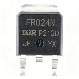
IRLR024NTRPBF - 55V 17A N-Channel HEXFET MOSFET | Infineon
MPN: IRLR024NTRPBF ✓ Active| Qty | Unit Price | Extended |
|---|---|---|
| 1 | $0.92 | $0.92 |
| 10 | $0.83 | $8.30 |
| 100 | $0.71 | $71.00 |
| 500 | $0.58 | $290.00 |
| 1,000 | $0.46 | $460.00 |
IRLR024NTRPBF Overview
An N-channel HEXFET MOSFET (Metal-Oxide Semiconductor Field Effect Transistor) is a voltage-controlled three-terminal switch in which the gate voltage modulates a conductive channel between drain and source. Logic-level MOSFETs are specifically designed to fully enhance at VGS values of 4.5 V or lower, allowing direct drive from 3.3 V or 5 V microcontrollers without bootstrap or gate-driver stages. HEXFET refers to Infineon's (formerly International Rectifier) trademarked hexagonal cell layout that reduces on-resistance per unit silicon area. Within the broader taxonomy, this part belongs to the power MOSFET > discrete semiconductor > power management ecosystem.
Key features include a low 65 mOhm Rds(on) for reduced conduction loss, a 10 nC typical total gate charge for fast switching transitions, a 55 V drain-to-source breakdown voltage with avalanche energy rating, and 100% lead-free construction. The logic-level gate threshold (1.0 V to 2.0 V typical) ensures full turn-on from 5 V MCU logic, while the fully-isolated DPAK tab eliminates the need for additional insulating hardware during PCB mounting.
Internally, the device uses a vertical DMOS structure with a hex-cell layout that minimizes cell pitch and maximizes channel density. The low gate charge (Qg) of 10 nC enables operation at switching frequencies above 500 kHz with manageable driver losses. The combination of low Rds(on) and low Qg yields an excellent figure-of-merit (FOM = Rds(on) × Qg) suitable for both hard-switched and soft-switched converter stages.
Typical applications include DC motor drive and H-bridge circuits, low-voltage synchronous rectification in switched-mode power supplies (SMPS), solenoid and relay drivers, battery protection circuits in 12 V lead-acid and multi-cell Li-ion packs, and general-purpose load switching in industrial automation and consumer appliances.
When designing with this MOSFET, observe safe operating area (SOA) limits during inductive switching, add a TVS or RC snubber across drain-source for avalanche protection, and ensure the gate driver can source/sink the 10 nC Qg within the required rise/fall time. Thermal management must account for the 45 W Tc rating and the package's RthJA of approximately 50 C/W on a 1 oz copper 1 in² pad.
Drop-in alternatives for IRLR024NTRPBF — same package, pin-to-pin compatible. Different-package parts requiring PCB rework are excluded.
Variants in this series
Same-series models that are drop-in compatible with IRLR024NTRPBF (same form factor and footprint) — differing in Package, Technology, FET Type, MSL Level, Total Gate Charge (Qg).
Quick Comparison Tool — Select alternative parts for side-by-side comparison:
IRLR024NTRPBF
✅ Drop-In✓ In Stock
$0.46 / Unit
View Datasheet →IRLR024N
✅ Drop-In📋 Reference alternative (not in catalog)
IRFR024NTRPBF
✅ Drop-In ⚠️ 参数待验证✓ In Stock
$0.31 / Unit
View Datasheet →IRLL024ZTRPBF
✅ Drop-In✓ In Stock
$0.46 / Unit
View Datasheet →IRLR8721TRPBF
✅ Drop-In ⚠️ 参数待验证📋 Reference alternative (not in catalog)
NTD24N06L
✅ Drop-In📋 Reference alternative (not in catalog)
IRLR024NTRPBF Maximum Ratings & Electrical Characteristics
| FET Type | N-Channel MOSFET, Metal Oxide |
| Drain-to-Source Voltage (Vdss) | 55 V |
| Continuous Drain Current (Id) at Tc=25C | 17 A |
| Rds(on) Max @ Vgs=10V | 65 mOhm |
| Gate Threshold Voltage (Vgs(th)) | 1.0 V to 2.0 V |
| Total Gate Charge (Qg) | 10 nC (typical) |
| Power Dissipation (Pd) at Tc=25C | 45 W |
| Operating Temperature Range | -55 C to +175 C |
| Mounting Type | Surface Mount |
| Package | TO-252AA (DPAK) |
| Technology | HEXFET (Advanced Process Technology) |
| Avalanche Rated | Yes (fully avalanche rated) |
| Gate Drive Level | Logic-Level |
| Lead-Free / RoHS | Lead-Free / RoHS Compliant |
| MSL Level | 1 (per JEDEC J-STD-020) |
IRLR024NTRPBF Pin Configuration
| Pin 1 | Gate — MOSFET gate control input (logic-level) |
| Pin 2 | Drain — MOSFET drain (internally connected to metal tab) |
| Pin 3 | Source — MOSFET source |
| Pin TAB | Drain — Metal tab, electrically tied to pin 2 (Drain); used as thermal pad for PCB heatsinking |
Safe Operating Area - IRLR024N
Typical Applications
IRLR024NTRPBF is suitable for 7 applications: 12V / 24V DC Motor Drive, Synchronous Rectification in Low-Voltage SMPS, Battery Protection & Load Switching, Solenoid & Relay Driver, Power Tool & Appliance Motor Control, LED Lighting Driver, Automotive 12V Load Switching.
12V / 24V DC Motor Drive
The IRLR024NTRPBF is well-suited to drive 12 V and 24 V brushed DC motors in H-bridge or low-side switch topologies. With Vdss=55 V it provides 30 V headroom above a 24 V nominal bus - sufficient margin for inductive flyback spikes. The 17 A continuous drain current handles motors up to ~200 W, while the logic-level gate threshold (Vgs(th) = 1.0-2.0 V) means a 3.3 V or 5 V MCU GPIO can drive the gate directly without an external driver IC, reducing BOM cost and PCB area. Pair with a 10-100 ohm gate resistor to limit ringing and add a flyback diode across the motor for relay-style drive. The DPAK tab provides adequate heatsinking at moderate duty cycles.
Recommended
Synchronous Rectification in Low-Voltage SMPS
In buck converters and forward converters with output voltages below 24 V, the IRLR024NTRPBF can replace a Schottky rectifier as a synchronous rectifier to reduce conduction loss. Rds(on)=65 mOhm at full Vgs yields lower drop than a Schottky diode at currents above ~3 A. The 10 nC total gate charge keeps gate-drive losses manageable at switching frequencies up to 500 kHz. The 55 V Vdss provides comfortable margin for 24 V outputs with ringing transients. For highest efficiency, drive the gate from a synchronized PWM controller output with proper dead-time insertion to prevent shoot-through.
Recommended
Battery Protection & Load Switching
Multi-cell Li-ion battery packs and 12 V lead-acid systems commonly use the IRLR024NTRPBF as a low-side load switch or charge/discharge disconnect MOSFET. The 55 V rating covers 4S Li-ion (16.8 V max) and 12 V/24 V lead-acid systems, while 17 A continuous current supports moderate-power load shedding. Logic-level gate drive allows the battery management IC to drive the MOSFET directly. Avalanche rating and -55 C to +175 C operating range support harsh automotive under-hood environments. Place a TVS diode across drain-source to clamp inductive transients from motors or solenoids.
Recommended
Solenoid & Relay Driver
Industrial automation and appliance controls use the IRLR024NTRPBF as a low-side driver for 12 V and 24 V solenoids, valves, and small relays. The 17 A Id rating covers most solenoid inrush currents, and the 55 V Vdss withstands inductive kickback spikes that can exceed 100 V on a 24 V system without snubbing. Logic-level gate drive enables direct control from a 5 V PLC output or microcontroller. Add a flyback diode (e.g., 1N5404) or a TVS across the solenoid for unclamped inductive switching protection. The DPAK package allows compact PCB integration inside DIN-rail enclosures.
Recommended
Power Tool & Appliance Motor Control
Cordless power tools, kitchen appliances, and small industrial equipment benefit from the IRLR024NTRPBF's combination of high current, logic-level gate drive, and surface-mount DPAK packaging. In PWM-variable-speed drills or blender-motor controllers, this MOSFET switches at 20-50 kHz with low switching loss thanks to 10 nC Qg. The 17 A continuous rating handles motors up to ~150 W continuous. Surface-mount construction enables automated assembly and reduces manufacturing cost versus through-hole alternatives. For higher-power tools (>500 W), consider paralleling two IRLR024NTRPBF or upgrading to a TO-220 part like IRLZ24NPBF.
Recommended
LED Lighting Driver
High-brightness LED drivers and architectural lighting systems use the IRLR024NTRPBF as a low-side PWM dimming switch or buck-converter power stage. Its 17 A current capability drives LED strings up to ~200 W, while 55 V Vdss handles 36 V and 48 V LED strings with adequate transient headroom. Logic-level gate drive enables direct PWM dimming from a microcontroller at frequencies above 1 kHz, exceeding the flicker-fusion threshold. The DPAK package's exposed tab provides sufficient heatsinking for continuous LED drive currents of 5-8 A in compact fixture form factors.
Recommended
Automotive 12V Load Switching
Automotive body electronics use the IRLR024NTRPBF for switching headlights, fans, pumps, and accessory loads on 12 V systems. The 55 V Vdss handles load-dump transients up to 35 V with margin, and the -55 C to +175 C junction range supports under-hood and chassis-mounted applications. The 17 A current rating covers most automotive accessory loads. While this part is not AEC-Q101 qualified (the Q101-graded variant is recommended for production automotive designs), it serves prototyping and non-safety automotive applications effectively. Logic-level gate drive enables direct control from body-control modules.
Recommended
Recommended Products Summary
Engineering reference data for IRLR024NTRPBF — comparison, design guidance, and compliance information.
Selection Guide
Comparison with Alternatives
| Parameter | This Product | IRLR024N | IRFR024NTRPBF | IRLL024ZTRPBF | NTD24N06L |
|---|---|---|---|---|---|
| Package | TO-252AA (DPAK) | TO-252AA (DPAK) - same | TO-252AA (DPAK) - same | TO-252AA (DPAK) - same | TO-252AA (DPAK) - same |
| Brand | Infineon | Infineon | Infineon | Infineon | onsemi |
| Vdss (Drain-Source Voltage) | 55 V | 55 V | 55 V | 55 V | 60 V |
| Continuous Drain Current (Id) at Tc=25C | 17 A | 17 A | 17 A | 17 A | 24 A |
| Gate Threshold Voltage (Vgs(th)) | 1.0 V to 2.0 V | 1.0 V to 2.0 V | 1.0 V to 2.0 V | 1.0 V to 2.0 V | 1.0 V to 2.5 V |
| Logic-Level Gate Drive | Yes | Yes | Yes | Yes | Yes |
| Avalanche Rated | Yes | Yes | Yes | Yes | Yes |
Key Differentiators
- Logic-level gate drive compatible with 5V MCU (vs Standard N-channel MOSFETs)
- Compact DPAK surface-mount package (vs Through-hole TO-220 alternatives (IRLZ24NPBF))
- Wide operating temperature range (vs Consumer-grade MOSFETs (0 to +150 C))
Design Notes
The IRLR024NTRPBF is rated for 45 W at Tc=25 C, but at the board level with a 1 oz copper 1 in² DPAK pad the effective power dissipation is limited by theta_JA (~50 C/W). Estimate: at 1 A continuous load and 5 V drop (P=5 W), the junction rises approximately 250 C - clearly above the 175 C limit, so the practical board-level limit is closer to 2-3 A continuous. For higher currents, increase the copper pad area or use thermal vias to inner layers. The tab is internally tied to the drain - the pad is at drain potential, so PCB layout must respect high-voltage spacing requirements.
Use a gate series resistor (10-100 ohm) to dampen the LC resonance between the gate capacitance and parasitic lead/trace inductance. Without this resistor, fast gate transitions can produce >2x overshoot on the gate-source voltage and cause ringing. Place the gate resistor within 5 mm of the gate pin. Keep the gate-drive loop area (gate resistor to gate pin to source pin back to driver return) as small as possible to minimize EMI. The source pin (pin 3) should be the return reference for the gate driver, not the tab.
Estimated thermal rise: at Vds=24 V bus, Id=10 A pulsed, 50% duty cycle, average power = Vds × Id × duty / 2 = 60 W peak dissipation (pulsed) - confirm against single-pulse SOA curve before designing. The single-pulse SOA of this 55 V/17 A part is limited at high Vds - the DC SOA curve drops to ~0.5 A at 55 V Vds. For linear-mode operation (e.g., hot-swap controller) the part must operate within the DC SOA, not the pulsed SOA. Always include a TVS diode or RC snubber across drain-source for unclamped inductive switching protection.
Compliance Information
Lead-free / RoHS compliant per Infineon product page. Not AEC-Q100/Q101 qualified - for automotive production designs select an AEC-Q101-graded variant. REACH compliant per manufacturer declaration.