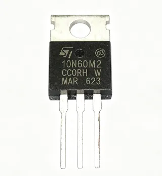
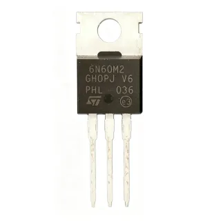
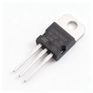
STP160N3LL - 30V 120A 2.5mOhm N-Ch MOSFET | STMicroelectronics
MPN: STP160N3LL ✓ Active| Qty | Unit Price | Extended |
|---|---|---|
| 1 | $1.85 | $1.85 |
| 10 | $1.66 | $16.60 |
| 100 | $1.42 | $142.00 |
| 500 | $1.2 | $600.00 |
| 1,000 | $0.98 | $980.00 |
STP160N3LL Overview
A power MOSFET is a voltage-controlled semiconductor switch in which the gate field modulates conduction between drain and source. As a member of the discrete semiconductors family (alongside diodes, thyristors and IGBTs), it is the workhorse of power electronics, sitting within the hierarchy: MOSFET -> transistor -> discrete semiconductor. The STP160N3LL is a low-voltage, high-current switching transistor optimized for efficiency-critical power stages.
Its headline feature is the very low 2.5 mOhm typical RDS(on), which directly minimizes conduction losses (P = I2 x R) in high-current paths. The 120 A / 136 W ratings and 175 C maximum junction temperature provide substantial thermal margin. Rth(j-case) of 1.1 C/W allows efficient heat transfer to a heatsink in TO-220 through-hole mounting.
Technically, the STripFET H6 trench gate structure achieves low on-resistance with reduced gate charge (60 nC typical) and input capacitance (4200 pF), enabling faster switching and lower switching losses than planar MOSFET designs. These parameters matter for gate-drive sizing and switching-frequency selection in synchronous rectification and DC-DC conversion.
Typical applications include synchronous rectification in high-efficiency power supplies, DC-DC converters, motor control, and battery management systems where low conduction loss at 30 V-class rails is essential.
Design tip: drive the gate with the specified 10 V gate-source voltage to fully enhance the channel and achieve the 2.5 mOhm figure; keep high-current PCB loops short and wide to limit parasitic inductance, and budget a heatsink based on actual dissipation.
Drop-in alternatives for STP160N3LL — same package, pin-to-pin compatible. Different-package parts requiring PCB rework are excluded.
Quick Comparison Tool — Select alternative parts for side-by-side comparison:
STP110N3LL
✅ Drop-In ⚠️ Specs Unverified📋 Reference alternative (not in catalog)
VBM1301
✅ Drop-In📋 Reference alternative (not in catalog)
SPP100N03S2-03
✅ Drop-In📋 Reference alternative (not in catalog)
SPP80N03S2L04AKSA1
✅ Drop-In📋 Reference alternative (not in catalog)
IPP018N03L
✅ Drop-In ⚠️ Specs Unverified📋 Reference alternative (not in catalog)
STP160N3LL Maximum Ratings & Electrical Characteristics
| Technology | STripFET H6 trench gate |
| Drain-Source Voltage (VDS) | 30 V |
| Continuous Drain Current (ID) | 120 A at Tc=25C |
| On-Resistance (RDS(on)) typ | 2.5 mOhm |
| Total Power Dissipation (Ptot) | 136 W at Tc=25C |
| Gate Charge (Qg) typ | 60 nC |
| Input Capacitance (Ciss) | 4200 pF |
| Maximum Junction Temperature | 175 C |
| Thermal Resistance Junction-Case | 1.1 C/W |
| Polarity | N-channel |
| Package | TO-220 |
| Mounting Type | Through Hole |
| RDS(on) at 4.5 V VGS | 4.2 mOhm max |
| RoHS Status | Compliant |
| Lead Free | Yes |
STP160N3LL Pin Configuration
| Pin 1 | Gate — Gate control terminal |
| Pin 2 | Drain — Drain terminal, connected to TO-220 metal tab |
| Pin 3 | Source — Source terminal |
Safe Operating Area (VDS vs ID)
Typical Applications
STP160N3LL is suitable for 6 applications: Synchronous Rectification in Power Supplies, DC-DC Converters, Motor Control and Drives, Battery Management Systems, Automotive and Industrial Power Switching, Load Switches and Hot-Swap Power Paths.
Synchronous Rectification in Power Supplies
The STP160N3LL's 2.5 mOhm typical RDS(on) makes it ideal for secondary-side synchronous rectification in 12 V-output AC-DC and DC-DC power supplies, where conduction loss (I2 x R) dominates at high output currents. At 100 A, conduction loss is only about 25 W, dramatically better than Schottky diode solutions. Placed as a low-side rectifier with a 10 V gate drive, it achieves lowest on-resistance; its 30 V VDS rating provides margin against secondary leakage spikes with adequate snubbing.
Recommended
DC-DC Converters
In high-current 12 V to low-voltage point-of-load converters, the STP160N3LL serves as the low-side or high-side switch. Its 60 nC gate charge and 4200 pF Ciss keep gate-drive losses manageable at 100-300 kHz switching frequencies, while trench-gate technology reduces switching losses versus planar devices. With 120 A capability and 136 W dissipation at Tc=25C, it supports multi-hundred-watt converter stages when heatsink-mounted with the 1.1 C/W Rth(j-case) exploited by forced-air cooling.
Recommended
Motor Control and Drives
The STP160N3LL fits 12-24 V DC motor drive H-bridges and BLDC inverters where low RDS(on) reduces heat in confined housings. Its trench STripFET H6 structure offers fast switching, reducing transition losses during PWM commutation, and the 120 A rating handles motor stall and acceleration currents. Designers should add freewheeling protection via the body diode or external Schottky, and keep gate loops short to limit ringing; a 10 V drive ensures the 2.5 mOhm figure under full load current.
Recommended
Battery Management Systems
As the main discharge/charge path switch in 12 V lead-acid or 4S lithium battery systems, the STP160N3LL's 2.5 mOhm on-resistance keeps series loss and voltage drop minimal at high pack currents, protecting runtime and accuracy of current sensing. Its 30 V rating covers transient conditions during load dump in 12 V automotive-adjacent systems. Battery protection FETs conduct continuously, so thermal design using the 1.1 C/W junction-to-case resistance and a heatsink is essential for sustained 60-100 A loads.
Recommended
Automotive and Industrial Power Switching
The through-hole TO-224 strength of the STP160N3LL suits rugged industrial and vehicle 12-24 V switching applications such as solenoid drivers, heater controls, and DC contactor replacements. The 120 A capability and 175 C junction rating provide robust derating margins in high-ambient environments, and the through-hole package supports screw-mounted heatsinks for high dissipation. Note the standard STP160N3LL is not AEC-Q100 listed in the provided data; verify qualification requirements before automotive production use.
Recommended
Load Switches and Hot-Swap Power Paths
For high-current ORing and hot-swap power paths on 12 V rails, the STP160N3LL acts as the series pass element where its 2.5 mOhm RDS(on) yields only 125 mV drop at 50 A, preserving downstream voltage accuracy. The 60 nC gate charge allows controlled inrush slew via gate RC networks, and its SOA supports current-limiting intervals during hot-insertion events. Pair with a controller providing fast overcurrent trip to keep single-pulse SOA within the 136 W device envelope.
Recommended
Recommended Products Summary
Engineering reference data for STP160N3LL — comparison, design guidance, and compliance information.
Selection Guide
Comparison with Alternatives
| Parameter | This Product | STP110N3LL | VBM1301 | SPP100N03S2-03 | SPP80N03S2L04AKSA1 |
|---|---|---|---|---|---|
| Package | TO-220 | TO-220 - same | TO-220 - same | TO-220 - same | TO-220 - same |
| Brand | STMicroelectronics | STMicroelectronics | Vishay (per source) | Infineon | Infineon |
| Drain-Source Voltage | 30 V | 30 V | 30 V | 30 V | 30 V |
| Technology | STripFET H6 trench | STripFET trench | Trench | OptiMOS trench | OptiMOS trench |
Key Differentiators
- Highest current rating in the comparison set (vs SPP100N03S2-03)
- Ultra-low on-resistance from STripFET H6 (vs STP110N3LL)
- Trade-off: through-hole TO-220 only (vs SPP80N03S2L04AKSA1)
Design Notes
At 100 A conduction with 2.5 mOhm RDS(on), loss is 25 W. With 1.1 C/W Rth(j-case), the junction rises only 27.5 C above case, but case-to-ambient resistance of a bare TO-220 is ~50 C/W, so a heatsink is mandatory above a few watts. Size the heatsink so Tj stays below 175 C with margin; derate RDS(on) upward with temperature (roughly 1.5x at 125 C) in loss calculations.
Although the STP160N3LL is through-hole, the gate-drive loop must still be short and wide. Place the gate driver close to the gate pin, include a 10-20 Ohm gate resistor to damp ringing, and use a low-ESR gate-source pulldown (10 kOhm) to prevent floating-gate turn-on during handling. Bolt the tab to a heatsink with thermal paste and verify tab (drain) isolation requirements.
Do not drive the gate at logic levels (4.5 V) if you need the 2.5 mOhm typical figure - at 4.5 V VGS, RDS(on) max is about 4.2 mOhm, a 68 percent conduction-loss increase. Also respect the 30 V VDS limit: add snubbers or clamps in inductive switching circuits, since leakage spikes above 30 V will avalanche and can destroy the die at high current.
Compliance Information
RoHS compliant and lead-free per STMicroelectronics internal description. REACH and halogen-free status not stated in provided data.