Logic ICs
Products (361)

SN74ABT244APWRE4 - Octal 3-State Buffer 5V TSSOP-20 | TI
The Texas Instruments SN74ABT244APWRE4 is an octal non-inverting buffer/driver with 3-state outputs, operating from a 4.5 V to 5.5 V supply in a 20-pin TSSOP (PW) surface-mount package. It is organized as two 4-bit buffer elements with independent output-enable (OE) controls, delivering TTL-compatible drive for heavily loaded 5V buses. A buffer and line driver is a digital logic device that provides signal amplification, fan-out expansion, and isolation between a low-drive controller and high-capacitance loads. Within the logic hierarchy, line drivers sit between simple gates and full bus transceivers, providing unidirectional buffering with output enable control for bus-oriented systems. The 244 configuration is the industry-standard octal non-inverting buffer pinout. Key features include Advanced BiCMOS (ABT) EPIC-II process technology that significantly reduces power dissipation compared to earlier bipolar families, 3-state outputs that allow direct connection to shared bus lines, and separate active-low OE1 and OE2 pins controlling the two 4-bit halves independently. Outputs are rated for high capacitive drive, making the part ideal for memory address driving and clock distribution. According to TI, the family targets 3-state memory address drivers, clock drivers, and bus-oriented receivers and transmitters. The ABT architecture combines CMOS input logic with bipolar output transistors, giving the device TTL-compatible CMOS inputs, fast propagation delays, and robust output current capability at 5V operation. The PW package offers a compact 6.4 mm body with 0.65 mm pin pitch for space-constrained boards. Typical applications include 5V microprocessor bus buffering, memory address and data line driving, industrial I/O module isolation, and backplane driver stages in legacy 5V systems. For design, tie unused OE inputs to VCC through a pull-up to keep outputs in the high-impedance state during power-up, and decouple VCC with 0.1 uF ceramics. This page synthesizes distributor pricing, drop-in alternatives, pinout data, and practical design notes not found in the manufacturer datasheet alone.
SN74ABT244APWRG4 - Octal 3-State Buffer 5V TSSOP-20 | TI
The Texas Instruments SN74ABT244APWRG4 is an octal non-inverting buffer/line driver with 3-state outputs, operating from a 4.5V to 5.5V supply with a typical propagation delay of 4.6 ns, housed in a 20-pin TSSOP (PW) package rated from -40C to +85C. A line driver or buffer is a logic device that strengthens digital signals for transmission across buses, long PCB traces, or cables where fan-out, capacitive loading, or noise would otherwise corrupt data. Buffers sit within the broader logic IC hierarchy: gate -> buffer/driver -> bus transceiver -> logic IC. The 244 family is the industry-standard octal buffer topology, splitting its eight channels into two independently enabled 4-bit groups so one device can serve two separate buses or provide bidirectional-by-direction-control buffering. Key features of the SN74ABT244A include TTL-compatible CMOS inputs, 3-state outputs that tri-state for bus sharing, and a drive capability suited to heavily loaded backplanes. The device belongs to TI's BiCMOS ABT (Advanced BiCMOS Technology) family, which combines the low static power of CMOS with the high drive current and speed of bipolar output stages, significantly reducing power dissipation compared with older bipolar-only drivers. Technically, the ABT family uses TI's EPIC-BiCMOS process, providing output current levels capable of driving 50 pF loads while keeping propagation delays in the nanosecond range, and includes livable latch-up immunity and partially powered operation behavior typical of ABT parts (driving outputs while VCC is absent is a classic ABT benefit for hot-insertion-style designs). Typical applications include microprocessor and DSP address/data bus buffering, memory interface isolation, backplane driving in industrial control systems, and general 5V TTL logic level strengthening in instrumentation. Design consideration: always decouple VCC with a 0.1uF ceramic capacitor close to pin 20, and use the two /OE pins to guarantee 3-state condition during power sequencing or bus arbitration. This page adds value beyond the TI datasheet by synthesizing drop-in alternatives, pricing tiers, comparison tables, and practical design notes in one place.

SN74AC574DWR - Octal D-Type Edge-Triggered F-F, 3-State | TI
The Texas Instruments SN74AC574DWR is an octal D-type edge-triggered flip-flop with 3-state outputs, housed in a 20-pin SOIC (DW) package with a body width of 0.295" (7.50 mm). It operates from a 2 V to 6 V VCC supply, is fabricated in TI's AC (Advanced CMOS) logic family, and is rated for -40C to +85C commercial operation. Each device contains eight D-type flip-flops sharing a single positive-edge-triggered clock input and an Output Enable (OE) input that places all outputs in a high-impedance state when asserted. What is a D-type edge-triggered flip-flop? A flip-flop is a bistable memory element that captures one bit of data. An edge-triggered D-type flip-flop latches its D input value on the rising edge of the clock and holds that value stable until the next rising edge. When implemented in octal form with shared clock and OE controls, these devices serve as synchronous storage registers commonly used to capture multi-bit parallel data arriving from a bus, sensor array, or processor port. The 3-state output stage allows multiple octal registers to share a common bus without contention, which is why this topology is pervasive in microprocessor and DSP glue logic. Key features of the SN74AC574 include a typical clock frequency rating that supports high-speed bus interfaces, 3-state outputs designed specifically for driving highly capacitive or relatively low-impedance loads directly, and inputs that tolerate voltages up to 6 V maximum. These devices are particularly suitable for implementing buffer registers, I/O ports, bidirectional bus drivers, and working registers - the canonical applications for an octal registered buffer. From an architecture standpoint, the SN74AC574 builds on TI's AC advanced CMOS process, which delivers balanced drive strength and lower power dissipation than legacy bipolar or HC families at comparable speeds. Compared with non-edge-triggered latches (such as the '573), edge-triggered '574 removes the critical setup/hold timing pitfalls of transparent latches and is preferred wherever a registered output is needed on a synchronous clock domain. Typical applications include microprocessor and microcontroller bus expansion (registering address or data lines), memory interface buffering (capturing data into FIFO or RAM arrays), I/O port expansion for industrial controllers, LED drive registers, and parallel ADC/DAC data capture. The wide 2 V to 6 V supply range also makes the part compatible with both 3.3 V and 5 V system rails. When designing with this device, designers should pay attention to the SOIC-20 land pattern, the required clock pulse width per the datasheet timing table, and the OE timing relative to clock edges to avoid bus contention during asynchronous resets. The 'DW' (SOIC-20) suffix supports standard reflow soldering and reel packaging for high-volume assembly. This page synthesizes distributor pricing, drop-in pin-compatible alternatives from Texas Instruments and ON Semiconductor, and practical design notes not aggregated in the manufacturer datasheet alone.

SN74ACT373-EP - Octal D-Type Transparent Latch | Texas Instruments
The SN74ACT373-EP is an Enhanced Product octal D-type transparent latch with 3-state outputs from Texas Instruments, designed for driving highly capacitive or relatively low-impedance loads. This 8-bit latch operates over a wide VCC range of 4.5V to 5.5V, with inputs that accept voltages up to 5.5V and are TTL-voltage compatible. The device features a buffered output-enable (OE) input that places the eight outputs in either a normal logic state or a high-impedance state, enabling bus-organized systems without the need for interface or pullup components. An octal D-type transparent latch is a digital logic component that captures the state of eight data inputs (1D-8D) when the latch-enable (LE) input is high, and holds that state when LE is low. The 3-state outputs allow multiple devices to share a common bus, as each output can be disabled (high-impedance) to avoid contention. This device is part of the ACT family, which combines advanced CMOS technology with TTL-compatible inputs, offering high speed and low power consumption. Key features include a maximum propagation delay (tpd) of 5V, 3-state outputs for bus driving, and compatibility with TTL voltage levels. The Enhanced Product designation indicates extended temperature range and reliability for demanding applications. The device is available in multiple package options, including SOIC, SSOP, TSSOP, and PDIP, providing design flexibility. Technically, the SN74ACT373-EP uses a CMOS process that provides balanced propagation delays and high noise immunity. The 3-state outputs are controlled by the OE input, which when low, enables the outputs; when high, places them in high-impedance state. This allows the latch to drive bus lines directly, reducing the need for external buffers. The device also features a latch-enable (LE) input that is level-sensitive, making it transparent when high and latched when low. Typical applications include address latching in microprocessor systems, data buffering in memory interfaces, and general-purpose I/O expansion. The high drive capability and 3-state outputs make it ideal for bus-oriented designs where multiple peripherals share a common data bus. The wide operating temperature range of -40°C to 125°C (Enhanced Product) ensures reliable operation in industrial and automotive environments. When designing with this device, ensure that the OE and LE inputs are properly driven to avoid bus contention. The high-impedance state should be used to prevent multiple outputs from driving the same bus simultaneously. Additionally, consider the propagation delay and setup/hold times to meet system timing requirements.

SN74AHC08RGYR - Quad 2-Input AND Gate, 14-VQFN | Texas Instruments
The Texas Instruments SN74AHC08RGYR is a quadruple 2-input positive-AND gate from the AHC (Advanced High-speed CMOS) logic family, housed in a 14-pin VQFN (RGY) package with 3.5 mm x 3.5 mm body and an exposed thermal pad. It performs the Boolean function Y = A · B (positive logic) across four independent gates, supports a 2 V to 5.5 V VCC operating range, and delivers a typical propagation delay of 9 ns at 5 V, making it well-suited for high-speed glue logic. An AND gate is a fundamental combinational logic primitive that produces a logic-high output only when all of its inputs are logic-high; in CMOS families it is built from a pull-up PMOS network in series with a pull-down NMOS network. Within the broader hierarchy, the AND gate belongs to logic gates -> combinational logic -> standard logic ICs -> integrated circuits. The AHC family sits between the slower HC (CMOS) and the lower-power AUC family, optimized for balanced speed and low static power dissipation in mixed 3.3 V / 5 V systems. Key features include ±8 mA output drive at 5 V, low static power consumption with ICC typically below 20 µA, and 5 V-tolerant inputs that allow safe interfacing with 3.3 V logic rails. The device offers robust ESD protection exceeding 2000-V HBM (JESD22-A114), 200-V MM, and 1000-V CDM models, plus latch-up immunity exceeding 250 mA per JESD 17. Schmitt-trigger action at the inputs ensures clean switching on slowly rising signals. Typical applications include industrial control signal gating, bus interfacing, power-up sequencing logic, address decoding, and general-purpose glue logic in microcontroller-based designs. The wide 2 V to 5.5 V supply range and balanced speed/power profile make it ideal for portable battery-powered equipment as well as mains-powered industrial controllers. When designing with this part, place 0.1 µF decoupling capacitors close to the VCC pin and tie unused inputs to VCC or GND to avoid floating inputs and undefined output states per TI application-note guidance. The exposed thermal pad should be soldered to a copper pour for improved mechanical reliability and thermal performance.

SN74AHC1G00DBVR - 2-5.5V Single 2-Input NAND Gate | Texas Instruments
The SN74AHC1G00DBVR is a single 2-input positive-NAND gate from Texas Instruments, designed for 2-V to 5.5-V operation. It performs the Boolean function Y = A NAND B in positive logic and is housed in a 5-pin SOT-23 (DBV) surface-mount package, making it ideal for space-constrained designs requiring low power and high noise immunity. A NAND gate is a fundamental digital logic gate that outputs LOW only when all inputs are HIGH. It is a universal gate, meaning any other logic function (AND, OR, NOT, XOR) can be built from NAND gates alone. The SN74AHC1G00 belongs to the AHC (Advanced High-Speed CMOS) logic family, which balances speed and power for battery-powered and portable systems within the broader CMOS logic IC hierarchy. Key features include a wide 2-V to 5.5-V operating range, a maximum propagation delay of 6.5 ns at 5 V, and maximum quiescent supply current of only 10 uA. Schmitt-trigger action on all inputs provides hysteresis-based noise immunity, allowing slow input edges without false triggering and eliminating external conditioning components. The device delivers ±8 mA output drive at 5 V, compatible with standard CMOS and TTL logic levels. Fabricated in advanced CMOS technology, the SN74AHC1G00 combines high-speed switching with low static and dynamic power dissipation. Robustness features include latch-up performance exceeding 250 mA per JESD 17 and ESD protection exceeding 2000-V HBM, 200-V MM, and 1000-V CDM ratings per the TI datasheet. Typical applications include signal gating, logic inversion, clock gating, and interface buffering in consumer electronics, industrial control, and automotive subsystems. The small SOT-23-5 footprint suits wearables, IoT modules, and dense PCBs where board area is at a premium. Design tip: do not let input voltages exceed VCC, and decouple the VCC pin with a 0.1-uF ceramic capacitor for best noise performance. Pricing shown reflects distributor data as of 2026-08-29.
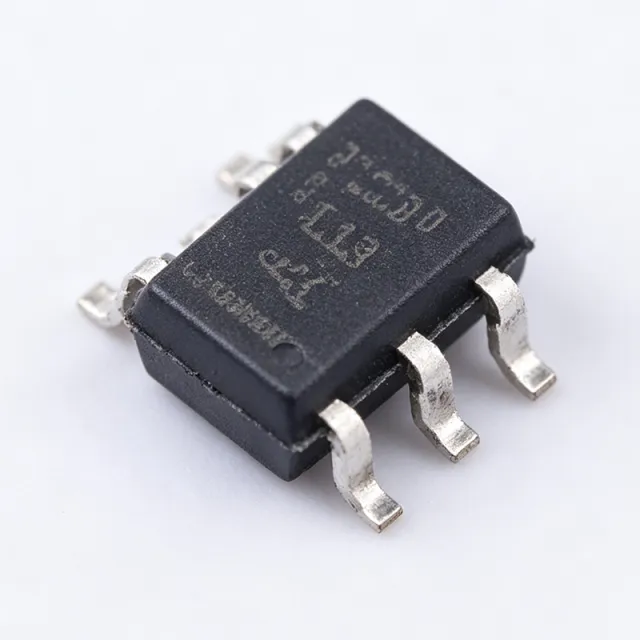
SN74AHC1G08-Q1 - Automotive 2-Input AND Gate SC-70-5 | TI
The Texas Instruments SN74AHC1G08-Q1 is an automotive-qualified single 2-input positive-AND gate that performs the Boolean function Y = A AND B in positive logic. Operating from a 2V to 5.5V supply, the device delivers a maximum propagation delay of 9 ns at 5V and comes in a 5-pin SC-70 (DCK) surface-mount package. A single-gate logic IC integrates exactly one logic function - here an AND gate - in a tiny footprint, unlike traditional quad-gate devices such as the 74HC08. Single-gate devices sit within the broader CMOS logic IC family, under combinational logic, and are widely used for glue logic, signal gating, and enable generation in modern PCBs where board space is at a premium. Key features include the AHC family's balanced CMOS architecture for low static power consumption, a wide 2V to 5.5V operating range supporting both 3.3V and 5V systems, and latch-up performance exceeding 250 mA per JESD 17. ESD protection exceeds 2000-V Human-Body Model, 200-V Machine Model, and 1000-V Charged-Device Model per TI datasheet. The -Q1 suffix denotes AEC-Q100 qualification for automotive applications. The AHC technology provides TTL-compatible CMOS outputs with balanced drive and fast switching, while the unbuffered single-stage design keeps propagation delay tight and predictable across the operating range. Typical applications include automotive body electronics and cluster gating, industrial PLC I/O conditioning, and general-purpose enable/signal gating in mixed 3.3V/5V systems. Design tip: keep unused input pins tied to VCC or GND, and place a 0.1uF decoupling capacitor close to the VCC pin to ensure clean switching edges and minimize ground bounce in automotive noise environments.

SN74AHC1G08DBV3 - 1-Ch 2-Input AND Gate, 2-5.5V | TI
The Texas Instruments SN74AHC1G08DBV3 is a single-channel, 2-input positive-AND gate from the AHC (Advanced High-Speed CMOS) logic family, housed in a 5-pin SOT-23 (DBV) package. It operates from a 2 V to 5.5 V supply, supports propagation delay of 9 ns maximum at 5 V (per TI's product page), and provides ±8 mA output drive at 5 V for driving moderate loads. The device performs the Boolean function Y = A · B in positive logic, making it a fundamental building block for digital decision-making and signal gating. An AND gate is a basic combinational logic gate that produces a HIGH output only when all of its inputs are HIGH. Logic gates are the fundamental building blocks of digital integrated circuits, sitting at the lowest level of the digital design hierarchy: logic gate -> combinational logic -> sequential logic -> microcontroller / ASIC. The AHC family is a higher-speed, lower-power evolution of the classic HC (High-Speed CMOS) family, designed for low static power consumption while delivering faster switching than HC and lower switching noise than TTL. Key features include a wide 2 V to 5.5 V operating range, ±8 mA balanced output drive at 5 V, 10 µA maximum quiescent supply current (Icc), and a Schmitt-trigger action on the inputs that makes the device tolerant of slowly rising edges. The SOT-23-5 footprint (DBV) is one of the industry's smallest logic-gate packages, enabling high-density board layouts in space-constrained designs. The device is also characterized for operation over the -55 °C to +125 °C free-air temperature range, suitable for industrial and harsh-environment applications. Internally, the SN74AHC1G08 uses a standard CMOS push-pull output stage with a buffered input. The Schmitt-trigger input hysteresis typically exceeds 1 V at 5 V, which improves noise immunity in environments with slow or noisy input edges. The wide Vcc range allows the part to translate logic levels between 3.3 V and 5 V domains without external level shifters, useful when interfacing microcontrollers, sensors, and older 5 V peripherals. Typical applications include power-rail sequencing and control logic in portable and battery-powered devices, enabling logic and control in industrial sensor interfaces, level shifting between 3.3 V and 5 V rails, general-purpose glue logic in microcontroller-based embedded designs, and signal gating in test and measurement equipment. The wide supply range and small package make it a versatile companion to virtually any digital subsystem. When designing with this device, place a 0.1 µF decoupling capacitor as close as possible to the Vcc pin and minimize input trace lengths to avoid noise-induced glitches. Because this is a non-inverting AND function, be aware that it cannot be used as a NAND; if inverted output is required, cascade with an inverter such as SN74AHC1G04 in the same SOT-23-5 package. This page synthesizes distributor pricing, drop-in same-package alternatives, and design guidance not always present in the manufacturer datasheet, providing actionable engineering reference for selection, replacement, and layout.

SN74AHC373PWR - Octal Transparent D-Type Latch | TI | 20-TSSOP
The Texas Instruments SN74AHC373PWR is an octal transparent D-type latch with 3-state outputs, operating from 2V to 5.5V VCC, housed in a 20-pin TSSOP (PW) package. It provides eight D-type latches organized as a single 8:8 channel with non-inverting transparent latch behavior, controlled by a latch-enable (LE) input and an active-low output-enable (OE) bar input that places outputs in high-impedance state. A latch is a sequential storage element that captures data when the latch-enable is asserted and holds it transparently or in storage mode. As a member of the AHC (Advanced High-speed CMOS) family, this device is pin-compatible with the HC (High-speed CMOS) logic family while delivering lower static power and faster switching at 5V operation. The latches occupy a position in the logic hierarchy between simple flip-flops and bus-oriented register files, making them ideal for address/data bus demultiplexing, I/O port expansion, and state retention in microcontroller-based systems. Key features include a typical propagation delay of 8.5 ns at 5V, support for +/-8 mA output drive, and ESD protection exceeding JESD 22 (2000V human-body model, 200V machine model, 1000V charged-device model). The device offers low power consumption with a typical quiescent current of 4 uA, supports +/-50 mA bus-hold and bus-drive, and provides true 5V tolerant inputs on a 2V-5.5V supply rail. Internally, the SN74AHC373 uses eight transparent D latches each with a 3-state output buffer. When LE is HIGH, the latch is transparent and follows the D input; when LE falls LOW, the value is stored. The OE bar pin enables the output buffers; when OE bar is HIGH, outputs are high-impedance. This architecture is widely used as a simple 8-bit data register or address demultiplexer. Typical applications include LED driving via 8-bit port expansion, address demultiplexing in microcontroller memory interfaces, bus isolation in mixed-voltage systems, and general-purpose 8-bit data storage. The wide 2V-5.5V range enables direct interfacing between 3.3V MCUs and 5V peripherals. When designing with this part, ensure that OE bar is properly tied to GND through a pull-down resistor if not actively driven, to prevent floating outputs. Unused D inputs should be tied to VCC or GND to avoid floating CMOS inputs. The TSSOP-20 package has a low thermal resistance suitable for industrial temperature operation. This page synthesizes distributor pricing, drop-in alternatives from same-brand and cross-brand vendors, and practical design notes not found in the manufacturer datasheet.

SN74AHC3G99-Q1 - Triple Configurable Logic Gate AEC-Q100 | TI
The Texas Instruments SN74AHC3G99-Q1 is an automotive-grade triple ultra-configurable multiple-function gate containing three independent configurable logic gates, each with four inputs and a 3-state output, implementing the Boolean function Y = (A • C + B • C) ⊕ D. It operates over a 2V to 5.5V supply range, making it compatible with 3.3V and 5V logic systems, and is qualified per AEC-Q100 for automotive environments. Configurable logic gates are digital ICs that let a single device implement multiple Boolean functions - MUX, AND, OR, NAND, NOR, XOR, XNOR - depending on input connections. They belong to the standard logic gate family within digital ICs, the fundamental building blocks of digital electronics. Integrating three such gates in one package saves board space and simplifies inventory versus discrete gates. Key features include Schmitt-trigger inputs on every pin, which eliminate erroneous outputs caused by slow-edged or noisy input signals - critical in electrically harsh automotive systems. The 3-state outputs place pins in a high-impedance state, enabling bus sharing. Per the TI datasheet, the device drives load capacitance up to 50pF while meeting all datasheet specifications, with a typical propagation delay of 7.5ns at 5V for high-speed operation. Technically, the device is built on TI AHC (Advanced High-Speed CMOS) technology, balancing speed with low static power consumption. Input hysteresis improves noise immunity and permits slow input transitions without false triggering, while output-enable control supports bus-oriented architectures. Typical applications include automotive body control modules, infotainment systems, and industrial automation where multiple logic functions are required in a compact footprint. It also suits signal conditioning in mixed-voltage systems. Design tip: keep total output load capacitance at or below 50pF to preserve full datasheet timing, and place a 0.1uF decoupling capacitor close to VCC to suppress supply noise.

SN74AHC9541-Q1 - AEC-Q100 Octal Buffer, Schmitt | TI
The Texas Instruments SN74AHC9541-Q1 is an automotive-grade octal buffer and line driver featuring Schmitt-trigger inputs and 3-state outputs, qualified to AEC-Q100 for harsh automotive environments. It operates from a 2V to 5.5V supply, supports -40C to +125C ambient temperatures, and is offered in a wettable-flank QFN (VSSOP-20) package that enables reliable solder-joint inspection. An octal buffer is a digital logic IC providing eight independent buffering channels that isolate, amplify, and restore digital signals. Buffers sit within the standard logic family hierarchy (CMOS logic > buffers/line drivers > single gates), preventing loading effects on driving circuits and regenerating weak or degraded signals across PCB traces, cables, and backplanes. Schmitt-trigger inputs add hysteresis, converting slow or noisy input edges into clean, fast output transitions. Key features include the wide 2V to 5.5V operating range compatible with 3.3V and 5V logic systems, dual active-low output enables (OE1 and OE2) that must both be low to activate all eight outputs, and AEC-Q100 automotive qualification. According to the TI datasheet, the device drives loads with total capacitance up to 50pF while meeting all datasheet specifications; larger loads may be applied but exceeding 50pF is not recommended. Fabricated in AHC-series CMOS technology, the device delivers low static power consumption, high speed, and balanced drive. The wettable-flank QFN package improves wetting of the package edge during soldering and enables automated optical inspection (AOI), a key automotive quality requirement. Typical applications include automotive body control modules, infotainment systems, ADAS signal buffering, and industrial interfaces where slow or noisy signals must be conditioned or held during controller reset. Design tip: keep per-output capacitive loading at or below 50pF, place 0.1uF decoupling capacitors close to VCC, and tie unused inputs to VCC or GND - never leave CMOS inputs floating.

SN74AHCT3G99-Q1 - Triple Configurable Gate | TI | Automotive
The SN74AHCT3G99-Q1 is an automotive-grade triple ultra-configurable multiple-function gate from Texas Instruments, containing three independent configurable logic gates with 3-state outputs in a 20-pin TSSOP (PW) package. Each gate has four inputs and implements the Boolean function Y = (A • /C + B • C) ⊕ D, which users can configure for functions such as MUX, AND, OR, NAND, NOR, XOR, and XNOR by appropriately strapping the inputs. A configurable multiple-function gate is a logic IC that can be wired to perform different Boolean operations, allowing one device to replace several fixed-function gates and reducing component count and board space. In the digital logic hierarchy it belongs to the configurable standard logic family, a subset of logic ICs within the broader category of integrated circuits. The SN74AHCT3G99-Q1 is part of the AHCT family - high-speed silicon-gate CMOS with TTL-compatible inputs - bridging CMOS efficiency and TTL logic levels. Key features include Schmitt-trigger inputs on all pins, which eliminate erroneous outputs caused by slow-edged or noisy input signals, and 3-state outputs that permit bus-oriented applications with high-impedance isolation. The supply range is 4.5V to 5.5V for full datasheet performance, and the device is AEC-Q100 qualified with an operating temperature range of -40C to +125C for harsh automotive environments. TI specifies the device can drive a total load capacitance of up to 50pF while meeting all datasheet specifications; larger loads are possible but not recommended. Technically, the device is fabricated in advanced CMOS, providing low static power consumption with TTL-level input thresholds. Propagation delay is [DATA_NEEDED: propagation delay] and output drive current is [DATA_NEEDED: output drive current]. The 3-state outputs are controlled via output-enable (OE) inputs, and Schmitt-trigger hysteresis of [DATA_NEEDED: hysteresis voltage] ensures clean switching on slow edges. Typical applications include automotive body control modules, infotainment units, and industrial control systems needing flexible glue logic, signal routing, or level-compatible logic functions. AEC-Q100 qualification guarantees reliability under automotive temperature, vibration, and ESD stress. When designing with this device, place decoupling capacitors close to the supply pins, keep output load capacitance at or below 50pF, and tie every OE input to a defined logic level to avoid floating bus contention.
SN74AHCT7541-Q1 - Automotive Octal Buffer, Open-Drain | TI
The SN74AHCT7541-Q1 from Texas Instruments is an automotive-grade octal buffer with open-drain outputs, operating from a 4.5V to 5.5V supply in a 20-pin TSSOP (PW) package. It contains eight non-inverting buffers with active-low output enable pins (OE1 and OE2); both enables must be low for the outputs to be active. When enabled, outputs actively drive low or present a high-impedance state; when disabled, outputs are high impedance. The device is AEC-Q100 qualified for a +125C ambient grade with HBM ESD protection. An octal buffer is a digital IC providing eight independent buffer channels used to increase fan-out, drive capacitive loads, or interface between voltage domains. With open-drain outputs, the device sinks current to ground when active, which makes it ideal for driving LEDs and implementing wired-OR logic. Schmitt-trigger inputs add hysteresis for superior noise immunity in automotive and industrial environments. Key features include the 4.5V to 5.5V supply range, open-drain outputs suited to external pull-up voltages above VCC, and inputs that tolerate slow edge rates thanks to Schmitt-trigger hysteresis. Per the TI datasheet, the device drives loads with total capacitance up to 50pF while meeting all datasheet specifications; larger capacitive loads are possible but not recommended. Output low-level current capability is defined by the VOL/IO characteristics in the Electrical Characteristics table. Technically, the device uses Advanced High-Speed CMOS TTL-compatible (AHCT) technology, balancing speed and power. External pull-up resistors define the output high level, a critical design consideration for wired-OR buses and mixed-voltage interfacing. The -40C to +125C operating range suits under-hood and body-electronics environments. Typical applications include automotive dashboard indicator LED drivers, level shifting between 5V and higher-voltage domains, wired-OR interrupt lines, and industrial control I/O requiring high noise immunity. Design tip: size pull-up resistors for the desired high level and sink current, tie OE1/OE2 appropriately, and place a 0.1uF decoupling capacitor close to the VCC pin.

SN74ALS253 - Dual 4:1 Mux 3-State ALS TTL | Texas Instruments
The Texas Instruments SN74ALS253 is a dual 1-of-4 data selector/multiplexer with 3-state outputs, fabricated in Advanced Low-Power Schottky (ALS) TTL technology and offered in 16-pin packages including Plastic DIP (N), Small-Outline (D), ceramic chip carrier (FK), and ceramic J packages. Each half multiplexes one of four data inputs to a single 3-state output under two common select lines, with separate active-low output-control (OE) inputs per section. A multiplexer is a combinational logic device that selects one of several input signals and forwards it to a single output, serving as a fundamental building block in the digital logic hierarchy between basic gates and larger bus-oriented logic systems. The 74-family lineage spans standard TTL (74), Schottky (74S), Low-Power Schottky (74LS), Advanced Low-Power Schottky (74ALS), and CMOS variants such as 74HC and 74HCT. Key features include full binary decoding with internal inverters and drivers feeding AND-OR gate structures, 3-state outputs that directly drive bus-organized data lines, and the ALS speed-power advantage over LS parts: faster propagation with substantially lower supply current. It is the 3-state version of the ALS153 and SN74AS153, permitting multiplexing from n lines to one line and parallel-to-serial conversion. Typical applications include bus-organized system data selection, parallel-to-serial data conversion, n-line to 1-line multiplexing in industrial controllers, and legacy TTL system maintenance and repair where ALS-era timing margins must be preserved. Design consideration: as an older bipolar TTL family, the SN74ALS253 requires a regulated 5V supply and presents TTL-level input thresholds; when integrating into mixed-voltage modern designs, verify logic-level compatibility or consider CMOS substitutes such as 74HC253 with attention to timing.
SN74ALVCH162373 - 16-Bit 3-State Transparent Latch | TI
The Texas Instruments SN74ALVCH162373 is a 16-bit transparent D-type latch with 3-state outputs, part of the ALVCH low-voltage CMOS Widebus family. It operates from a 2.3V to 3.6V supply and can function as two independent 8-bit latches or one 16-bit latch, controlled by latch-enable (LE) and output-enable (OE) inputs. When LE is high, the Q outputs follow the D inputs; when LE is low, the outputs hold the last data. A transparent latch is a sequential logic component that passes input data to outputs while enabled and stores the last value when disabled. It sits in the hierarchy: transparent latch -> D-type latch -> latch -> sequential logic -> digital logic IC, and is a fundamental building block for data storage, synchronization, and bus interfacing in digital systems. Key features include bus-hold circuitry on data inputs, which eliminates external pull-up or pull-down resistors; equivalent 26-ohm series resistors on output ports, removing the need for external line-termination resistors; and latch-up performance exceeding 250 mA per JESD 17, plus ESD protection. The 3-state outputs allow multiple devices to share a common bus, and the Ioff feature supports partial-power-down operation without backflow current. Technically, the device uses advanced low-voltage CMOS technology, providing high speed with low static power consumption. Propagation delay is typically around 4.1 ns at 3.3V, with +/-12 mA output drive at 3.3V, suitable for moderate capacitive loads. It is characterized for operation from -40C to +85C in industrial environments. Packages include 48-SSOP (DL), 48-TSSOP (DGG/GR), and 56-BGA MicroStar Junior (KR). Typical applications per the TI datasheet include buffer registers, I/O ports, bidirectional bus drivers, and working registers in memory interfaces, data acquisition systems, and general-purpose logic. Design tip: place 0.1uF decoupling capacitors close to each VCC pin, and verify timing margins since the integrated 26-ohm output resistors slightly slow edge rates at high frequencies.

SN74AUC2G34 - Dual Buffer Gate 0.8-2.7V | Texas Instruments
The Texas Instruments SN74AUC2G34 is a dual non-inverting buffer gate from the AUC (Advanced Ultra-CMOS) logic family, performing the Boolean function Y = A in positive logic. It operates from a 0.8 V to 2.7 V supply, specifically optimized for 1.65 V to 1.95 V operation, and is offered in the 6-pin SOT-23 (DBV) and SC70/SOT-563 (DCK) surface-mount packages for space-constrained portable designs. A buffer gate is a digital logic IC that passes its input to the output without inversion while regenerating drive strength and providing signal isolation. Within the logic-IC hierarchy (buffer gate -> logic IC -> digital integrated circuit), buffers are used to drive capacitive loads, isolate buses, and restore weak or degraded signal edges in low-voltage digital systems. Key features include sub-1-V operability, 3.6-V I/O tolerance for mixed-mode signal operation, and Ioff support for partial-power-down architectures. According to the TI datasheet (Rev. B), maximum propagation delay is 1.8 ns at 1.8 V with a +/-8-mA output drive at 1.8 V and low dynamic power consumption. NanoFree package technology in the smallest variants uses the die itself as the package. Architecturally, the device uses advanced ultra-low-voltage CMOS technology for high noise immunity and low static current. Ioff circuitry disables outputs and blocks damaging backflow current when VCC is removed while inputs remain driven - critical for multi-rail systems with flexible power sequencing. Typical applications include signal buffering in smartphones and tablets, clock distribution, 1.8 V to 3.3 V domain-tolerant interfacing, and bus isolation in industrial and consumer electronics. Design tip: place a 0.1 uF decoupling capacitor close to VCC and ensure input signals never exceed the absolute maximum rating of 4.6 V.

SN74AUP1G04DCKR - Low-Power Single Inverter | TI
The Texas Instruments SN74AUP1G04DCKR is a single inverter gate from the AUP (Advanced Ultra-Low-Power) logic family that performs the Boolean function Y = A̅, operating over a 0.8 V to 3.6 V VCC range and housed in a 5-pin SC-70 (DCK) package. An inverter gate is a single-input logic gate whose output is the logical complement of its input; it belongs to the broader category of logic gates within the digital IC hierarchy (logic gate -> combinational logic -> digital IC -> semiconductor). The AUP family is engineered specifically for battery-powered portable equipment where quiescent current draw and dynamic power consumption dominate battery life, making the SN74AUP1G04 well suited for applications that must remain powered continuously. Key features include a maximum quiescent current (ICC) of 0.9 µA, a typical dynamic power capacitance (Cpd) of 4.1 pF at 3.3 V, low input capacitance of 1.5 pF typical, and Schmitt-trigger action that keeps output noise (overshoot/undershoot) below 10 percent of VCC. Ioff circuitry supports partial-power-down by preventing damaging backflow current when the device is unpowered. The SC-70-5 footprint occupies approximately 2.0 mm x 1.25 mm on the PCB, supporting the densest of portable layouts. Internally, the SN74AUP1G04 uses a CMOS silicon-gate implementation that delivers rail-to-rail input and output swing, nanoStar and nanoFree package options, and an output drive of ±4 mA at 3.3 V. Typical propagation delay is around 4 ns at 3.3 V with a 30 pF load, which is fast enough for moderate-speed control and general-purpose logic glue but not optimized for high-speed buses. Typical applications include battery-powered portable medical devices, wearable fitness monitors, hand-held consumer electronics, ultra-low-power IoT sensor nodes, signal conditioning in microcontroller I/O expansion, and level translation between low-voltage MCU domains and 3.3 V peripherals. Designers use the SN74AUP1G04 wherever a single complementary logic signal is needed alongside an ultra-low-power MCU. When designing with this device, observe the recommended decoupling capacitor (0.1 µF ceramic) placed as close as possible to the VCC pin to control supply-induced jitter, and respect the absolute maximum VCC of 4.6 V to avoid latch-up. For partial-power-down rails, the Ioff feature removes the need for external protection diodes. This page synthesizes distributor pricing, same-brand and cross-brand drop-in alternatives from the AUP logic family, and practical design notes not found in the manufacturer datasheet alone. Pricing references are stated as of 2026-10-10.
SN74AUP1G14DRLR - 0.8V-3.6V Schmitt Inverter, SOT-553 | TI
The Texas Instruments SN74AUP1G14DRLR is a single-channel low-power Schmitt-trigger inverter in a 5-pin SOT-553 (DRL) package, designed for ultra-low-power operation from 0.8 V to 3.6 V VCC. According to TI's SN74AUP1G14 family datasheet, the device features 0.9 uA maximum quiescent current (ICC), 4.4 pF typical power dissipation capacitance (Cpd), and 1.5 pF typical input capacitance. Schmitt-trigger inputs provide hysteresis for noise immunity on slow or noisy edges. A Schmitt-trigger inverter is a logic gate that combines inversion with a hysteretic input threshold, preventing oscillation on slow or noisy input transitions. The AUP (Advanced Ultra-low Power) sub-family belongs to TI's CMOS logic portfolio, optimized for battery-powered and energy-harvesting applications. Within the logic hierarchy, inverters fall under gates -> combinational logic -> standard logic ICs. Schmitt-trigger variants are specifically designed for signal conditioning, oscillator circuits, and debouncing, where slow-rising signals (such as RC-filtered edges or mechanical switch closures) would otherwise cause multiple transitions on a standard CMOS input. Key features of the SN74AUP1G14 include partial-power-down capability through Ioff circuitry (preventing backflow current when the device is unpowered), NanoStar and NanoFree tiny package options, low overshoot/undershoot (<10% of VCC), and balanced 4 mA output drive at 3.3 V. The device is specified across the industrial -40C to +85C operating range and supports standard logic-level translation in mixed-voltage systems. The internal architecture uses TI's advanced CMOS process with hysteresis built into the input stage. The Schmitt-trigger threshold is approximately 0.65*VCC (rising) and 0.35*VCC (falling), giving roughly 30% VCC hysteresis. The Ioff feature protects downstream circuitry by blocking current paths through the I/O pins when VCC = 0 V, which is essential for systems where the SN74AUP1G14DRLR is powered down while the upstream bus remains live. Typical applications include button debouncing in handheld devices, RC relaxation oscillators, level translation between 1.8 V and 3.3 V domains, and signal conditioning for sensors. The 5-pin SOT-553 footprint is among the smallest single-gate packages available, making the device ideal for space-constrained wearables and IoT sensor nodes. When designing with this device, ensure input signal rise/fall times are slower than the typical CMOS transition rate to benefit fully from the Schmitt-trigger hysteresis. Place a 0.1 uF decoupling capacitor as close as possible to the VCC pin to suppress noise-induced threshold violations. This page consolidates distributor pricing, AEO-optimized FAQs, SOT-553 drop-in alternatives, and practical PCB layout notes not all gathered on a single manufacturer datasheet page.

SN74AUP1G240DBVT - Low-Power 3-State Inverter Buffer | TI
The Texas Instruments SN74AUP1G240DBVT is a single low-power inverting buffer/line driver with a 3-state output, operating from a 0.8 V to 3.6 V supply in a 5-pin SOT-23 (DBV) surface-mount package. It delivers a maximum propagation delay of 4.3 ns at 3.3 V and features 3.6 V tolerant I/O for mixed-signal operation. A buffer or line driver is a logic IC that strengthens, isolates, or inverts a digital signal without changing its logical state other than the intended inversion or buffering action. Within the voltage-regulation-and-signal-chain hierarchy, buffers belong to the standard logic family of CMOS digital ICs, sitting between microcontrollers or processors and loads that need extra drive current, signal isolation, or bus tri-stating. The AUP (Advanced Ultra-low Power) family is TI's premier solution for low static and dynamic power consumption across the full 0.8 V to 3.6 V VCC range, extending battery life in portable products. Key features include an ultra-wide 0.8 V to 3.6 V operating supply range, 3.6 V I/O tolerance that supports mixed-mode signal operation, a maximum propagation delay of 4.3 ns at 3.3 V, and latch-up performance exceeding 100 mA per JESD 17. The 3-state output places the /Y pin in a high-impedance state when /OE is high, enabling shared-bus and point-to-point architectures. Technically, the device uses CMOS circuitry optimized for very low dynamic power, maintaining excellent signal integrity even at reduced supply rails such as 1.2 V or 1.8 V, which are common in battery-powered portable applications. Typical applications include level-compatible signal buffering in smartphones, tablets, and wearables, bus isolation in battery-powered portable electronics, and point-to-point line driving in low-power industrial and IoT nodes. A key design consideration is that the /OE enable is active-low: pull /OE high to tri-state the output. Decouple VCC with a 0.1 uF ceramic capacitor close to pin 5. This page synthesizes distributor data, drop-in alternatives, pinout, and practical design notes not consolidated in the manufacturer datasheet.
SN74AUP1G32DCKR - Single 2-Input OR Gate, 0.8-3.6V AUP | Texas Instruments
The Texas Instruments SN74AUP1G32DCKR is a single 2-input positive-OR gate fabricated in TI's advanced ultra-low-power AUP (Advanced Ultra-low-Power) CMOS logic family, packaged in a 5-pin SC-70 (DCK) surface-mount package and supplied on tape-and-reel (R suffix). It operates over a 0.8 V to 3.6 V VCC supply range, consumes less than 1 uA of quiescent supply current (ICC max 0.9 uA), and delivers 4 mA typical output drive at 1.8 V VCC. An OR gate is a fundamental combinational logic building block that outputs a HIGH state whenever any of its inputs is HIGH; it sits within the broader Boolean logic IC hierarchy as one of the seven primitive gates and is foundational for implementing sum-of-products expressions, control signal arbitration, and discrete decision logic in digital systems. The AUP sub-family is optimized for battery-powered portable applications where leakage current dominates total power budget, providing CMOS-equivalent speed at one to two orders of magnitude lower static consumption than standard HC/HCT logic. Key features of the SN74AUP1G32DCKR include a propagation delay of approximately 3.4 ns typical at 3.3 V VCC (load-dependent), partial-power-down support via Ioff circuitry that prevents back-drive current when the device is unpowered, over-voltage tolerant inputs that accept signals up to 3.6 V regardless of VCC, low input capacitance of 1.5 pF typical for reduced dynamic loading, and ±10% VCC overshoot/undershoot immunity on switching edges. The push-pull CMOS output stage eliminates the need for external pull-up resistors required by open-drain alternatives, simplifying PCB layout. The AUP1G32 architecture uses a single-stage OR topology with internal buffering to ensure consistent output drive strength across the full VCC range. Its sub-1 uA ICC at 25 °C makes it among the lowest-leakage single-gate OR functions available, while the Ioff feature enables safe insertion into mixed-voltage rails and partial-power-down subsystems without latch-up. Typical applications include handheld consumer electronics, battery-powered sensor front-ends, IoT edge nodes, wearable devices, low-power MCUs as a logic-level adapter, and any compact PCB where a single discrete OR function is required alongside a multi-channel logic IC. Designers frequently pair the AUP1G32 with 1.8 V microcontrollers such as the MSP430 or SimpleLink families for status-flag combination, interrupt arbitration, and power-rail selection gating. When designing with this part, observe 3.6 V as the absolute maximum VCC and avoid DC loading on inputs above VCC; for high-speed paths above 50 MHz, verify propagation delay under actual load capacitance rather than relying on the typical datasheet figure. This page synthesizes distributor pricing, drop-in alternatives (same-package, pin-compatible), and practical design notes that are not aggregated on the manufacturer datasheet, enabling faster sourcing and replacement decisions for production engineers.

SN74AUP1T34-Q1 - 1-Bit Dual-Supply Level Translator | Texas Instruments
The Texas Instruments SN74AUP1T34-Q1 is a 1-bit unidirectional, noninverting voltage-level translator that operates from two separate configurable power-supply rails (VCCA and VCCB). It translates logic signals from A to B and comes in a 5-pin SC-70 (DCK) package qualified to AEC-Q100 for automotive applications, operating from -40C to +125C. A voltage-level translator is a logic IC that converts signals between two different voltage domains, allowing a 1.8V microcontroller to safely drive a 3.3V peripheral or vice versa. Translators sit within the broader logic IC family, alongside buffers, gates, and bus switches, and are essential wherever mixed-voltage systems interface. Key features include dual-supply operation enabling level translation in either direction (up or down), the AUP (Advanced Ultra-low Power) process family for very low dynamic power consumption, and push-pull output structure that removes the need for pull-up resistors required by open-drain translators. Per the TI datasheet, pin A is referenced to VCCA and receives the signal to be translated. The device belongs to TI's AUP1T single-gate translator family, which combines tiny single-gate packaging with wide supply flexibility, making it suitable for space-constrained automotive modules. The noninverting buffer topology preserves signal polarity with minimal propagation delay. Typical applications include automotive body electronics and lighting modules, level-shifting between 1.8V MCUs and 3.3V CAN or LIN transceivers, interfacing low-voltage sensors to higher-voltage logic, and general-purpose single-bit signal conversion in infotainment and cluster designs. Design consideration: ensure both supply rails are within the datasheet-recommended ranges and observe power-up sequencing guidance in the datasheet to avoid undefined outputs during startup. Because this is a unidirectional translator, the signal must always flow from pin A to pin Y/B.
SN74AUP1T34DSFR - 1-Bit Level Translator X2SON-6 | Texas Instruments
The Texas Instruments SN74AUP1T34DSFR is a 1-bit non-inverting unidirectional voltage-level translator in a 6-pin X2SON (DSF) package measuring 1x1 mm, operating over -40C to +85C. It uses two separate configurable power-supply rails, allowing logic signals to be translated between voltage domains such as 1.8V-to-3.3V or 1.2V-to-2.5V systems. A voltage-level translator is a member of the logic IC family (buffers, drivers, level translators within the broader category of digital integrated circuits) that converts digital signals from one logic-voltage domain to another. As process nodes shrink, modern MCUs, FPGAs, and sensors run on cores as low as 0.8V to 1.8V, while legacy peripherals, LEDs, and actuators still operate at 2.5V, 3.3V, or 5.5V. A dual-rail translator such as the SN74AUP1T34 bridges these domains safely, protecting input structures and guaranteeing valid logic levels on both sides. Key features include the AUP (Advanced Ultra-low Power) process family, known for the lowest dynamic power consumption in the TI small-signal logic portfolio, a push-pull (totem-pole) output that eliminates the need for an external pull-up resistor, and a non-inverting buffer function that preserves signal polarity. The tiny 1x1 mm X2SON footprint suits densely packed wearable, mobile, and IoT boards where every square millimeter counts. Technically, the device is a single-channel translator with the A port referenced to VCCA and the B port referenced to VCCB. Because the output is push-pull rather than open-drain, it delivers symmetric rise and fall times with lower static current than open-drain solutions. The Ultra-low-power AUP technology keeps dynamic power low during signal transitions, extending battery life in portable designs. Typical applications include GPIO level translation between microcontrollers and peripherals, I2C-adjacent and UART/SPI signal translation in portable consumer electronics, and interfacing low-voltage sensor outputs to higher-voltage logic in battery-powered IoT nodes. Design tip: power up VCCA before or together with VCCB and keep both rails within the datasheet-recommended operating window; decouple each rail with a 100 nF ceramic capacitor placed as close as possible to the pins to suppress transients on this compact package. This page synthesizes distributor pricing, drop-in alternatives, pinout detail, and practical design notes not found in a single manufacturer datasheet.
SN74AUP1T34QDCKRQ1 - AEC-Q100 1-Bit Level Translator | TI
The Texas Instruments SN74AUP1T34QDCKRQ1 is an AEC-Q100 qualified 1-bit unidirectional non-inverting voltage-level translator with dual configurable power-supply rails supporting VCCA and VCCB from 0.9V to 3.6V each, housed in a 5-pin SC-70 (DCK) surface-mount package rated from -40C to +125C. A voltage-level translator (also called a level shifter) is a logic IC that interfaces digital signals between circuits operating at different supply voltages, for example connecting a 1.8V microcontroller output to a 3.3V peripheral input. Level translators sit within the broader logic IC family (buffers, translators, transceivers) and are essential wherever mixed-voltage domains coexist, which is nearly every modern embedded system. Key features include two independent supply rails (VCCA and VCCB) that can each be set anywhere from 0.9V to 3.6V, allowing any-to-any translation between common logic levels such as 1.2V, 1.5V, 1.8V, 2.5V and 3.3V. The push-pull (non-inverting) output drives the signal actively in both directions, eliminating the need for external pull-up resistors required by open-drain solutions. The AUP (Advanced Ultra-low-Power) silicon technology delivers low dynamic power consumption, making the device attractive for battery-powered automotive and portable designs. Architecturally, pin A is referenced to VCCA and receives the input signal, while pin B is referenced to VCCB and transmits the level-shifted output. Because both supplies support the same 0.9V to 3.6V range, the translator is direction-agnostic in voltage terms: it can translate low-to-high or high-to-low. TI controls the data sheet SN74AUP1T34-Q1, and the -Q1 suffix denotes AEC-Q100 automotive qualification including extended -40C to +125C operation. Typical applications include automotive body electronics and ADAS sensor interfaces, I2C/SPI/UART signal translation between mixed-voltage ICs, GPIO level conversion in battery-powered portable equipment, and general-purpose 1-bit buffering in industrial control modules. Design consideration: both VCCA and VCCB must be decoupled with 0.1uF ceramic capacitors placed close to pins 4 and 5, and the unused input should never be left floating since the AUP family inputs must be tied high or low. This page adds value beyond the TI datasheet by synthesizing distributor pricing as of 2026-09-04, drop-in alternative analysis, and practical layout notes in one place.
SN74AUP2G126YZPR - Dual Bus Buffer 3-State 8-DSBGA | TI
The Texas Instruments SN74AUP2G126YZPR is a low-power dual bus buffer gate with 3-state outputs, offered in an 8-bump DSBGA (YZP) package. Each of its two channels is a non-inverting buffer with an independent output-enable input, allowing designers to place individual channels in a high-impedance state for bus-isolation or multiplexing duties. The AUP logic family targets battery-powered portable applications where dynamic and static current draw both matter. A bus buffer (or line driver) is a digital circuit element that reproduces a logic input at its output while providing higher drive strength, level translation, or bus-isolation capability. Within the broader taxonomy, a bus buffer belongs to the logic ICs category (sub-family: buffers/drivers/receivers) and falls under the CMOS logic umbrella alongside gates, inverters, and transceivers. Buffers are functionally distinct from transceivers: a buffer is unidirectional, while a transceiver is bidirectional and typically includes bus-side termination. The AUP family is TI's premier low-power CMOS sub-family, designed for sub-1 GHz edge rates and sub-microamp quiescent current budgets, sitting between the AUC (1.8-V optimized) and LVC (general-purpose) families in TI's logic-portfolio positioning. Key features include an operating voltage range of 0.8 V to 3.6 V across VCC, partial-power-down support via Ioff (live-insertion safe), 3.6-V tolerant inputs when VCC is at 3.3 V, low static and dynamic power consumption characteristic of AUP logic, and a maximum quiescent current in the microamp range. Each output stage uses TI's standard 3-state architecture, with an active-high output enable (OE) per channel. The 8-ball DSBGA package keeps the footprint extremely small - approximately 0.9 mm x 0.9 mm - making the part suitable for space-constrained wearables and handhelds. Architecturally, the SN74AUP2G126 uses TI's AUP silicon-gate CMOS process with industry-standard Schmitt-trigger inputs (partial), low-drive-strength CMOS outputs, and the Ioff feature that prevents back-feeding current into a powered-down output pin. Inputs are tolerant up to 3.6 V regardless of VCC, providing robust interface to 1.8 V, 2.5 V, and 3.3 V domain signals without external protection. Typical applications include smartphones and wearables, IoT sensor nodes, low-power portable instrumentation, voltage-level shifting between 1.2 V microcontrollers and 3.3 V peripherals, and any system needing bus multiplexing or isolation with minimal quiescent power. The 3-state outputs allow direct bus sharing with other drivers under careful OE arbitration. Designers should note that the DSBGA package requires reflow soldering with appropriate profile and that the small land pattern demands careful PCB layout and precise stencil design to avoid defects. When designing with this part, ensure that the OE pins are properly managed during power-up to prevent bus contention; pull OE to a defined logic level at startup rather than leaving them floating.