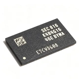
K9MDG08U5M - 16Gb x8 MLC NAND Flash TSOP1-48 | Samsung
MPN: K9MDG08U5M ✓ Active| Qty | Unit Price | Extended |
|---|---|---|
| 1 | $35.5 | $35.50 |
| 10 | $37 | $370.00 |
| 100 | $38.5 | $3,850.00 |
| 500 | $41.5 | $20,750.00 |
| 1,000 | $45 | $45,000.00 |
K9MDG08U5M Overview
NAND flash is a non-volatile memory technology organized as an array of pages and blocks, addressed through a multiplexed 8-bit I/O bus with command, address, and data latched sequentially via CLE, ALE, WE, and RE control signals. Within the memory hierarchy, NAND flash sits under the non-volatile memory family alongside NOR flash, and is typically managed by an ECC engine and flash translation layer in a host controller or SSD/eMMC solution.
Key characteristics of the K9MDG08U5M include its large-block MLC organization, x8 multiplexed address/data bus, stacked dual-die construction doubling capacity within the same TSOP1-48 footprint, and an operating voltage range of 2.7 V to 3.6 V per distributor data (Min Voltage 2.7 V, Max Voltage 3.6 V, 48 terminals).
Architecturally, the die uses Samsung MLC large-block NAND technology: pages are programmed sequentially and blocks must be erased before reprogramming. Because MLC cells have tighter read margins than SLC, system designers must implement ECC (for example BCH or LDPC depending on host capability) and wear-leveling firmware to guarantee data retention and endurance over the product lifetime.
Typical applications include USB flash drives, SD and CF memory cards, embedded storage modules, set-top boxes, and industrial data loggers where high density per dollar is the priority.
A key design consideration: MLC NAND tolerates fewer program/erase cycles than SLC, so endurance-critical designs should reserve spare blocks and monitor block wear. Page read and program timing must follow the datasheet tR/tPROG parameters with ready/busy polling via the R/B pin.
This page synthesizes distributor sourcing data, same-family drop-in alternatives such as K9HCG08U1M and K9LBG08U0M, and practical design notes not found in a single manufacturer datasheet.
Drop-in alternatives for K9MDG08U5M — same package, pin-to-pin compatible. Different-package parts requiring PCB rework are excluded.
Variants in this series
Same-series models that are drop-in compatible with K9MDG08U5M (same form factor and footprint) — differing in Package, Organization, Memory Type, Density, Interface.
Quick Comparison Tool — Select alternative parts for side-by-side comparison:
K9HCG08U1M
✅ Drop-In✓ In Stock
Contact for price
View Datasheet →K9LBG08U0M
✅ Drop-In📋 Reference alternative (not in catalog)
K9LCG08U1M
✅ Drop-In ⚠️ Specs Unverified✓ In Stock
$11.85 / Unit
View Datasheet →K9XXG08U0M
✅ Drop-In ⚠️ Specs Unverified✓ In Stock
$5.6 / Unit
View Datasheet →K9XXG08UXM
✅ Drop-In ⚠️ Specs Unverified✓ In Stock
Contact for price
View Datasheet →K9MDG08U5M Maximum Ratings & Electrical Characteristics
| Memory Type | MLC Large Block NAND Flash |
| Density | 16 Gbit (2 GB) |
| Organization | 16G x 8 bit |
| Cell Type | MLC (2 bits per cell) |
| Supply Voltage Min | 2.7 V |
| Supply Voltage Max | 3.6 V |
| Interface | Asynchronous x8 multiplexed address/data |
| Package | 48-pin TSOP1 dual stacked, 12 mm x 20 mm |
| Terminals | 48 |
| Circuits | 1 |
| Die Configuration | Dual stacked |
| Mounting Type | Surface Mount |
| RoHS Status | unknown |
K9MDG08U5M Pin Configuration
| Pin 1 | R/B — Ready/Busy output (open-drain) |
| Pin 2 | RE — Read enable |
| Pin 3 | CE — Chip enable |
| Pin 4 | NC — Not connected (per datasheet) |
| Pin 5 | NC — Not connected (per datasheet) |
| Pin 6 | NC — Not connected (per datasheet) |
| Pin 7 | NC — Not connected (per datasheet) |
| Pin 8 | NC — Not connected (per datasheet) |
| Pin 9 | NC — Not connected (per datasheet) |
| Pin 10 | NC — Not connected (per datasheet) |
| Pin 11 | CLE — Command latch enable |
| Pin 12 | ALE — Address latch enable |
| Pin 13 | WE — Write enable |
| Pin 14 | WP — Write protect |
| Pin 15 | NC — Not connected (per datasheet) |
| Pin 16 | NC — Not connected (per datasheet) |
| Pin 17 | NC — Not connected (per datasheet) |
| Pin 18 | NC — Not connected (per datasheet) |
| Pin 19 | NC — Not connected (per datasheet) |
| Pin 20 | NC — Not connected (per datasheet) |
| Pin 21 | NC — Not connected (per datasheet) |
| Pin 22 | NC — Not connected (per datasheet) |
| Pin 23 | VCC — Power supply (2.7 V to 3.6 V) |
| Pin 24 | VCC — Power supply (2.7 V to 3.6 V) |
| Pin 25 | NC — Not connected (per datasheet) |
| Pin 26 | NC — Not connected (per datasheet) |
| Pin 27 | NC — Not connected (per datasheet) |
| Pin 28 | NC — Not connected (per datasheet) |
| Pin 29 | I/O0 — Data input/output bit 0 |
| Pin 30 | I/O1 — Data input/output bit 1 |
| Pin 31 | I/O2 — Data input/output bit 2 |
| Pin 32 | I/O3 — Data input/output bit 3 |
| Pin 33 | VSS — Ground |
| Pin 34 | I/O4 — Data input/output bit 4 |
| Pin 35 | I/O5 — Data input/output bit 5 |
| Pin 36 | I/O6 — Data input/output bit 6 |
| Pin 37 | I/O7 — Data input/output bit 7 (also used for status/ID) |
| Pin 38 | NC — Not connected (per datasheet) |
| Pin 39 | NC — Not connected (per datasheet) |
| Pin 40 | NC — Not connected (per datasheet) |
| Pin 41 | VSS — Ground |
| Pin 42 | VSS — Ground |
| Pin 43 | NC — Not connected (per datasheet) |
| Pin 44 | NC — Not connected (per datasheet) |
| Pin 45 | NC — Not connected (per datasheet) |
| Pin 46 | NC — Not connected (per datasheet) |
| Pin 47 | NC — Not connected (per datasheet) |
| Pin 48 | NC — Not connected (per datasheet) |
Typical Applications
K9MDG08U5M is suitable for 6 applications: USB Flash Drives, SD and CF Memory Cards, Industrial Data Loggers, Set-Top Boxes and Embedded Storage, Firmware and Boot Storage, Consumer Electronics Backup Storage.
USB Flash Drives
The K9MDG08U5M provides 16 Gbit of MLC storage in a compact TSOP1-48 dual-stacked package, giving USB drive makers 2 GB per chip without stacking separate dies on the PCB. Its 2.7 V to 3.6 V single supply matches USB-powered controller rails directly through a 3.3 V LDO. The x8 multiplexed bus interfaces to standard USB NAND controllers with CLE/ALE/WE/RE handshake. The dual-stacked construction halves the number of solder joints versus two single-die packages, improving reliability at equivalent capacity. MLC economics keep the bill of materials competitive for consumer drives, provided the controller implements ECC and wear-leveling appropriate for MLC endurance limits.
Recommended
SD and CF Memory Cards
Memory card controllers pair naturally with the K9MDG08U5M because its 16 Gbit dual-stacked MLC density matches the 2 GB card generation in a single 48-pin TSOP1 footprint (12 mm x 20 mm) that fits card PCB height limits. The 2.7 V to 3.6 V range supports both 3.3 V card operation and dual-voltage controller designs. The asynchronous x8 NAND interface with ready/busy polling via R/B allows card controllers to optimize read-ahead and background erase. Because MLC read margins tighten over life, card firmware should schedule periodic data refresh. Designers should reserve spare blocks from the 2 GB array to sustain capacity after wear-out of defective blocks.
Recommended
Industrial Data Loggers
Veswin distributor data specifies the K9MDG08U5M-PCB0 over -40C to +105C (TA), enabling industrial data loggers deployed outdoors or in machinery enclosures to record sensor histories at 2 GB per chip. The 3.3 V class supply integrates with industrial 3.3 V microcontroller rails, and the WP pin provides write protection during brownout events, protecting log integrity at power failure. MLC endurance is adequate for logging applications where write frequency is moderate and wear-leveling spreads writes evenly. Extended-temperature retention should be verified against Samsung datasheet figures, and power-fail recovery logic should rely on the R/B ready/busy line to abort cleanly mid-page.
Recommended
Set-Top Boxes and Embedded Storage
Set-top box platforms use NAND like the K9MDG08U5M for firmware and PVR storage. Its 16 Gbit capacity comfortably holds bootloader, kernel, and application images with room for recording buffers, while the standard x8 asynchronous interface connects to common SoC NAND controllers without glue logic. The dual-stacked die is transparent to software beyond device-ID-based block addressing, allowing one PCB design to be populated with different densities from the same K9XXG08UXM family (for example K9LBG08U0M or K9HCG08U1M) to create product tiers. Firmware must implement BCH-class ECC because MLC read margins are tighter than SLC, plus bad-block management and boot-block mirroring for field reliability.
Recommended
Firmware and Boot Storage
For embedded boards booting from NAND, the K9MDG08U5M stores bootloader images at low cost with 2 GB available for field-updatable firmware images and settings. Most SoC boot ROMs read the first valid block from NAND using the same command set this device implements (0x00/0x30 read, 0x80/0x10 program, 0x60 erase), so no custom boot code is needed. Dual-stack addressing is handled via standard address cycles. Design practice: mirror the bootloader across two blocks, mark bad blocks in the spare area, and assert WP during power transitions. The 2.7 V to 3.6 V window must be maintained during program operations to guarantee write integrity.
Recommended
Consumer Electronics Backup Storage
Digital photo frames, portable media players, and voice recorders use the K9MDG08U5M as internal backup storage, where 2 GB of MLC NAND covers typical content libraries at minimal cost. The TSOP1-48 dual-stacked package keeps the PCB small for slim enclosures, and its 3.3 V supply operates directly from single-cell Li-ion via a buck/LDO stage. Battery-powered designs benefit from low read-current asynchronous operation; sustained program operations should be budgeted for power consumption estimates. Playback devices tolerate MLC latency because content is buffered in RAM, making the slower tR and tPROG of MLC versus SLC non-critical for this use case.
Recommended
Recommended Products Summary
Engineering reference data for K9MDG08U5M — comparison, design guidance, and compliance information.
Selection Guide
Comparison with Alternatives
| Parameter | This Product | K9HCG08U1M | K9LBG08U0M | K9LCG08U1M | K9XXG08U0M |
|---|---|---|---|---|---|
| Package | 48-pin TSOP1 dual stacked (12 x 20 mm) | 48-pin TSOP1 - same footprint | 48-pin TSOP1 - same footprint | 48-pin TSOP1 - same footprint | 48-pin TSOP1 - same footprint |
| Brand | Samsung Electronics | Samsung Electronics | Samsung Electronics | Samsung Electronics | Samsung Electronics |
| Supply Voltage | 2.7 V to 3.6 V | 2.7 V to 3.6 V | 2.7 V to 3.6 V | 2.7 V to 3.6 V | 2.7 V to 3.6 V |
| Cell Type | MLC (2 bits/cell) | MLC (2 bits/cell) | MLC (2 bits/cell) | MLC (2 bits/cell) | MLC (2 bits/cell) |
| Interface | x8 asynchronous multiplexed | x8 asynchronous multiplexed | x8 asynchronous multiplexed | x8 asynchronous multiplexed | x8 asynchronous multiplexed |
| Device ID / Generation | K9MDG (K9XXG08UXM family) | K9HCG (same family datasheet) | K9LBG (same family datasheet) | K9LCG (adjacent generation) | Series designation |
Key Differentiators
- Dual-stacked die doubles density per footprint (vs K9LBG08U0M)
- Extended-temperature industrial grade option (vs K9LCG08U1M)
- Same-family pin compatibility for capacity tiering (vs K9HCG08U1M)
Design Notes
Hold VCC within the 2.7 V to 3.6 V window at all times, especially during program and erase operations. Distributor data confirms the 2.7 V min / 3.6 V max range. Add 0.1 uF ceramic decoupling at each VCC pin pair plus 4.7-10 uF bulk near the package, since stacked-die parts draw combined current from both dies during tPROG. Brownout during a program operation corrupts the target page - assert WP low whenever the supervisor detects the supply leaving the valid window, and complete recovery via bad-block checking after power-up.
Never treat this MLC part like SLC: page program must proceed sequentially within a block, partial-page programming is restricted, and read margins require ECC. Read the device ID at boot and configure the flash translation layer for the actual page/block geometry rather than hardcoding, which also makes the design portable across K9HCG08U1M, K9LBG08U0M, and K9LCG08U1M drop-in family parts. Verify the ordering suffix (PCB0 vs PIB0) matches your validated speed grade before release.
Route the 8-bit I/O bus as a matched group with series termination (22-33 ohm) close to the controller to control ringing on the 12 mm x 20 mm TSOP1 stubs. Keep CLE/ALE/WE/RE short and reference a solid ground plane; the R/B pin is open-drain and needs a pull-up (typically 10 kohm) to VCC. Avoid routing I/O lines under the package center where possible, and provide thermal relief vias near VSS pins to handle erase-current spikes from the dual stacked dies.
Compliance Information
Compliance status not stated in the provided web data. Verify RoHS/REACH status on the official Samsung product page for the specific ordering suffix (PCB0/PIB0) before design-in.