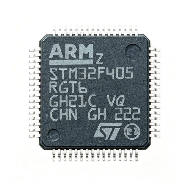
STM32F405RGT6 - 168MHz Cortex-M4F, 1MB Flash MCU | STMicroelectronics
MPN: STM32F405RGT6 ✓ Hoạt động| Số lượng | Giá đơn vị | Phụ |
|---|---|---|
| 1 | $11.5 | $11,50 |
| 10 | $10.2 | $102,00 |
| 100 | $8.85 | $885,00 |
| 500 | $7.6 | $3.800,00 |
| 1.000 | $6.75 | $6.750,00 |
STM32F405RGT6 Tóm tắt
A microcontroller (MCU) is a compact integrated circuit that combines a processor core, volatile and non-volatile memory, and programmable peripherals on a single silicon die to govern specific operations in embedded systems. The STM32F405RGT6 belongs to the STM32F4 mainstream performance line, which sits within the broader STM32 family of 32-bit Flash microcontrollers. The category hierarchy is MCU -> 32-bit MCU -> ARM Cortex-M MCU -> Cortex-M4 MCU -> STM32F4 MCU. MCUs are the central control element in industrial, consumer, medical, and IoT electronics.
Key features include 3x 12-bit ADCs (2.4 MSPS), 2x 12-bit DACs, 12x 16-bit timers plus 2x 32-bit timers, 51 GPIOs, and rich connectivity: 3x I2C, 4x USART plus 2x UART, 3x SPI, 2x CAN, USB 2.0 OTG Full-Speed and High-Speed with on-chip PHY, 100Mbit Ethernet, SDIO, and a DCMI camera interface. The device operates from 1.8V to 3.6V and includes a true random-number generator, hardware CRC unit, and a 96-bit unique device ID.
Technically, the chip uses a 90 nm CMOS process with an ART Accelerator enabling zero-wait-state execution from Flash, maximizing effective Cortex-M4 throughput. A memory protection unit supports robust firmware isolation, while multiple low-power modes (Sleep, Stop, Standby with RTC) allow energy optimization for battery-powered designs. The integrated USB OTG HS PHY and Ethernet MAC eliminate external PHY BOM cost for many designs.
Typical applications include field-oriented-control motor drives (FOC servo drives leveraging the FPU and DSP instructions), digital power conversion and PFC stages, industrial PLC and automation controllers, USB peripherals and audio devices, and consumer/medical products requiring real-time signal processing. The open-source STM32CubeIDE and STM32CubeMX ecosystem with HAL/LL libraries significantly shortens development cycles.
Design consideration: provide adequate 100 nF decoupling on every VDD/VSS pin pair, route USB HS D+/D- as a 90-ohm differential pair, and keep SDIO traces length-matched. Also note that Flash wait states apply above 168 MHz if the ART accelerator configuration is altered.
This page synthesizes distributor pricing, verified drop-in alternatives, and practical design notes not consolidated in the manufacturer datasheet.
Bộ thay thế dễ dàng lắp đặt cho STM32F405RGT6 — cùng gói, chân-to-chân tương thích. Các bộ phận yêu cầu hàn PCB bị loại trừ.
Các biến thể trong loạt này
Các mẫu cùng loạt có thể lắp đặt dễ dàng tương thích với STM32F405RGT6 (cùng hình factor và footprint) — khác nhau ở Core, Package, ADC, SRAM, Flash Memory.
Công cụ so sánh nhanh — Chọn các bộ phận thay thế để so sánh song song:
STM32F415RGT6
Liên hệ để biết giá
Xem tài liệu →STM32F405ZGT6
Liên hệ để biết giá
Xem tài liệu →STM32F405VGT6
Liên hệ để biết giá
Xem tài liệu →STM32F407VGT6
✗ Hết hàng
$7.55 / Đơn vị
Xem tài liệu →STM32F405RGT7
Liên hệ để biết giá
Xem tài liệu →GD32F405RGT6
📋 Tham chiếu thay thế (không có trong danh mục)
STM32F405RGT6 Tỷ lệ tối đa & tính chất điện
| Core | ARM Cortex-M4F (with single-precision FPU and DSP) |
| Tần số xung maksimum | 168 MHz |
| Performance | 210 DMIPS (1.25 DMIPS/MHz) |
| Flash Memory | 1 MB (1M x 8) |
| SRAM | 192 KB (including 4 KB backup SRAM) |
| Operating Voltage | 1.8 V to 3.6 V |
| Hộp | 64-LQFP (10x10 mm) |
| GPIO Count | 51 |
| ADC | 3x 12-bit, 2.4 MSPS, up to 24 channels |
| DAC | 2x 12-bit |
| Timers | 12x 16-bit + 2x 32-bit |
| Communication Interfaces | 3x I2C, 4x USART + 2x UART, 3x SPI, 2x CAN, USB OTG FS/HS, 100M Ethernet, SDIO, DCMI |
| Khoảng nhiệt độ hoạt động | -40C to +85C |
| Kiểu lắp đặt | Surface Mount |
| Trạng thái RoHS | Compliant |
| Lead-Free / Halogen-Free | Yes |
Cấu hình chân STM32F405RGT6
| Chân 1 | VBAT — Battery domain supply for RTC and backup SRAM |
| Chân 2 | PC13 — GPIO/Tamper-RTC (standard I/O with interrupt) |
| Chân 3 | PC14 — GPIO/OSC32_IN (32.768 kHz crystal) |
| Chân 4 | PC15 — GPIO/OSC32_OUT (32.768 kHz crystal) |
| Chân 5 | OSC_IN — HSE crystal/clock input |
| Chân 6 | OSC_OUT — HSE crystal output |
| Chân 7 | NRST — Reset input (active low) |
| Chân 8 | VSSA — Analog ground |
| Chân 9 | VDDA — Analog supply (1.8-3.6V) |
| Chân 10 | PA0-WKUP — GPIO/ADC0_IN0/Wakeup |
| Chân 11 | PA1 — GPIO/ADC0_IN1 |
| Chân 12 | PA2 — GPIO/USART2_TX/ADC0_IN2 |
| Chân 13 | PA3 — GPIO/USART2_RX/ADC0_IN3 |
| Chân 14 | PA4 — GPIO/SPI1_NSS/DAC_OUT1 |
| Chân 15 | PA5 — GPIO/SPI1_SCK/DAC_OUT2 |
| Chân 16 | PA6 — GPIO/SPI1_MISO/ADC1_IN2 |
| Chân 17 | PA7 — GPIO/SPI1_MOSI/ADC1_IN3 |
| Chân 18 | PB0 — GPIO/ADC2_IN8/TIM3_CH3 |
| Chân 19 | PB1 — GPIO/ADC2_IN9/TIM3_CH4 |
| Chân 20 | VSS_1 — Digital ground |
| Chân 21 | VDD_1 — Digital supply (1.8-3.6V) |
| Chân 22 | PB2/BOOT1 — GPIO/BOOT1 input |
| Chân 23 | PB10 — GPIO/I2C2_SCL/USART3_TX |
| Chân 24 | PB11 — GPIO/I2C2_SDA/USART3_RX |
| Chân 25 | VSS_2 — Digital ground |
| Chân 26 | VDD_2 — Digital supply (1.8-3.6V) |
| Chân 27 | PB12 — GPIO/SPI2_NSS/CAN2_RX |
| Chân 28 | PB13 — GPIO/SPI2_SCK/CAN2_TX |
| Chân 29 | PB14 — GPIO/SPI2_MISO/TIM12_CH1 |
| Chân 30 | PB15 — GPIO/SPI2_MOSI/TIM12_CH2 |
| Chân 31 | PA8 — GPIO/TIM1_CH1/USART1_CK/MCO |
| Chân 32 | PA9 — GPIO/USART1_TX/TIM1_CH2 |
| Chân 33 | PA10 — GPIO/USART1_RX/TIM1_CH3 |
| Chân 34 | PA11 — GPIO/USB_DM/CAN1_RX/TIM1_CH4 |
| Chân 35 | PA12 — GPIO/USB_DP/CAN1_TX/TIM1_ETR |
| Chân 36 | PA13 — GPIO/SWDIO |
| Chân 37 | VSS_3 — Digital ground |
| Chân 38 | VDD_3 — Digital supply (1.8-3.6V) |
| Chân 39 | PA14 — GPIO/SWCLK |
| Chân 40 | PA15 — GPIO/SPI3_NSS/TIM2_CH1 |
| Chân 41 | PC6 — GPIO/USART6_TX/TIM3_CH1 |
| Chân 42 | PC7 — GPIO/USART6_RX/TIM3_CH2 |
| Chân 43 | PC8 — GPIO/SDIO_D0/TIM3_CH3 |
| Chân 44 | PC9 — GPIO/SDIO_D1/TIM3_CH4 |
| Chân 45 | PA0 — GPIO/WKUP/USART2_CTS |
| Chân 46 | VDD_4 — Digital supply (1.8-3.6V) |
| Chân 47 | VSS_4 — Digital ground |
| Chân 48 | PB3 — GPIO/SPI3_SCK/TIM2_CH2 |
| Chân 49 | PB4 — GPIO/SPI3_MISO/TIM3_CH1 |
| Chân 50 | PB5 — GPIO/SPI3_MOSI/I2C1_SMBA |
| Chân 51 | PB6 — GPIO/I2C1_SCL/TIM4_CH1/USART1_TX |
| Chân 52 | PB7 — GPIO/I2C1_SDA/TIM4_CH2/USART1_RX |
| Chân 53 | BOOT0 — Boot mode select |
| Chân 54 | PB8 — GPIO/I2C1_SCL/CAN1_RX/TIM4_CH3 |
| Chân 55 | PB9 — GPIO/I2C1_SDA/CAN1_TX/TIM4_CH4 |
| Chân 56 | VSS_5 — Digital ground |
| Chân 57 | VDD_5 — Digital supply (1.8-3.6V) |
| Chân 58 | PD0 — GPIO/FSMC_D2/CAN1_RX |
| Chân 59 | PD1 — GPIO/FSMC_D3/CAN1_TX |
| Chân 60 | VREF+ — ADC positive reference |
| Chân 61 | VSSA — Analog ground |
| Chân 62 | VDDA — Analog supply |
| Chân 63 | PA13 — GPIO (secondary) |
| Chân 64 | VSS — Ground (additional) |
Ứng dụng tiêu biểu
STM32F405RGT6 phù hợp cho 7 Áp dụngs: Field-Oriented-Control Motor Drives, Industrial USB Host Peripherals, Digital Power Conversion and PFC, Audio Processing and DAC/ADC Interfaces, Industrial Ethernet Gateways, Consumer Medical Devices, Drones and Robotics Controllers.
Field-Oriented-Control Motor Drives
The STM32F405RGT6 fits FOC motor drives because the Cortex-M4F FPU and DSP instructions accelerate Park/Clarke transforms and PID loops by roughly 2-3x versus a Cortex-M3. The 168 MHz clock headroom leaves 30-40 percent CPU margin for encoder decoding and current-loop control. The 3x 12-bit ADCs sample phase currents at 2.4 MSPS, while the 12 timers provide complementary PWM with hardware dead-time insertion. Place a 100 nF decoupling cap on every VDD pin and route ADC inputs away from PWM switching nodes to preserve SNR.
Được đề xuất
Industrial USB Host Peripherals
The STM32F405RGT6 is widely used in industrial USB host peripherals because the integrated USB OTG Full-Speed and High-Speed PHY eliminates an external ULPI chip, reducing BOM by approximately USD 1-2. The Cortex-M4F core handles USB stack processing and application logic simultaneously. The SDIO controller and FSMC bus (on the F407 family variant) support external data buffering for printers, scanners, and data loggers. Designers should route the 90-ohm USB differential pair with length matching within 150 mil and add ESD protection diodes.
Được đề xuất
Digital Power Conversion and PFC
The STM32F405RGT6 is well-suited to digital power conversion and PFC stages because the Cortex-M4F single-precision FPU accelerates multiply-accumulate loops used in PID, state-space, and predictive control algorithms. The 12-bit ADCs sampled at 2.4 MSPS capture current and voltage waveforms with adequate bandwidth for PFC at 50-100 kHz switching. The high-resolution timer (217 ps) generates phase-shifted PWM for bridgeless PFC topologies. Plan 4-layer PCB layout to keep switching noise away from analog signal paths.
Được đề xuất
Audio Processing and DAC/ADC Interfaces
The STM32F405RGT6 serves audio processing applications because the Cortex-M4F SIMD instructions accelerate FFT, biquad, and dynamics processing at 48 kHz sample rates. The 2x 12-bit DACs and 3x 12-bit ADCs integrate codec functionality for budget audio products. The I2S-capable SPI port supports external 24-bit codecs. The 192 KB SRAM buffers multiple audio frames without external memory. Use DMA for both I2S RX and TX to keep the core free for DSP processing.
Được đề xuất
Industrial Ethernet Gateways
The STM32F405RGT6 fits industrial Ethernet gateways because the integrated 100 Mbit/s MAC and RMII interface connect to any standard Ethernet PHY for Modbus TCP, EtherNet/IP, or PROFINET. The Cortex-M4F core runs TCP/IP stacks plus application logic without external memory. The CAN 2.0B peripherals bridge fieldbus to enterprise networks. Pair with a wide-input DC-DC and provide 2 kV galvanic isolation on the Ethernet magnetics for industrial EMC compliance.
Được đề xuất
Consumer Medical Devices
The STM32F405RGT6 powers consumer medical devices like blood-pressure monitors, pulse oximeters, and spirometers because the Cortex-M4F core runs sensor-fusion DSP while the 12-bit ADC captures analog biosignals with 2.4 MSPS. The 1 MB Flash accommodates FDA-21CFR-Part-11 firmware with bootloader and OTA update. The USB OTG port provides powered device charging and data sync. Use the RTC with battery domain to maintain accurate timestamps across power cycles.
Được đề xuất
Drones and Robotics Controllers
The STM32F405RGT6 is a popular flight-controller MCU in hobbyist and commercial drones because the Cortex-M4F core runs Betaflight/Cleanflight/INAV firmware with full PID loops at 8 kHz update rates. The 168 MHz clock plus FPU computes quaternion math at rates that 72 MHz Cortex-M3 parts struggle to maintain. The 3x SPI ports connect to gyros, barometers, and radio receivers simultaneously. Mount the LQFP-64 with thermal vias to a copper pour for thermal relief at 50-60 mA active current.
Được đề xuất
Tóm tắt các sản phẩm được đề xuất
Dữ liệu tham khảo kỹ thuật cho STM32F405RGT6 — so sánh, hướng dẫn thiết kế và thông tin tuân thủ.
Hướng dẫn chọn lựa
So sánh với các sản phẩm thay thế
| Tham số | Sản phẩm này | STM32F415RGT6 | STM32F405RGT7 | STM32F405ZGT6 | GD32F405RGT6 |
|---|---|---|---|---|---|
| Brand | STMicroelectronics | STMicroelectronics | STMicroelectronics | STMicroelectronics | GigaDevice |
| Package | 64-LQFP (10x10 mm) | 64-LQFP (10x10 mm) - same | 64-LQFP (10x10 mm) - same | 144-LQFP (20x20 mm) | 64-LQFP (10x10 mm) - same |
| Core | Cortex-M4F @ 168 MHz | Cortex-M4F @ 168 MHz | Cortex-M4F @ 168 MHz | Cortex-M4F @ 168 MHz | Cortex-M4F @ 168 MHz |
| Flash | 1 MB | 1 MB | 1 MB | 1 MB | 1 MB |
| SRAM | 192 KB | 192 KB | 192 KB | 192 KB | 192 KB |
| Crypto/Hash Engine | No | Yes (AES, SHA) | No | No | No |
| Operating Temperature | -40C to +85C | -40C to +85C | -40C to +105C | -40C to +85C | -40C to +85C |
| GPIO Count | 51 | 51 | 51 | 114 | 51 |
| Approx. Unit Price (1k qty) | USD 6.75 | USD 7.40 | USD 6.95 | USD 9.10 | USD 3.20 (GigaDevice, LCSC) |
Bảo phân biệt quan trọng
- Integrated USB OTG High-Speed PHY (vsSTM32F103RCT6 (Cortex-M3))
- Single-precision FPU with DSP instructions (vsSTM32F103C8T6 (Cortex-M3))
- 1 MB Flash versus typical 256-512 KB Cortex-M3 baseline (vsGD32F103RCT6)
Ghi chú thiết kế
Provide a 100 nF decoupling capacitor on every VDD/VSS pin pair, placed within 2 mm of the pin. Add a bulk 4.7 uF ceramic near the VDD-1/VSS-1 cluster and a 10 uF tantalum or ceramic at the regulator output. For USB OTG HS operation, the internal PHY requires VDD-USB supply stable within 90 percent of nominal before the PLL is enabled, otherwise enumeration will fail. Estimated: assuming 100 mA active current at 3.3V, total power is 330 mW - the LQFP-64 theta_JA of approximately 50 C/W yields a 16C rise above ambient, well within safe limits.
Route the USB OTG HS D+/D- pair as a 90-ohm differential pair with length matching within 150 mil and no stubs. Keep the crystal traces short (under 5 mm) and guard them with a ground pour. The Ethernet RMII signals should be length-matched within 50 mil to the external PHY. SDIO traces must be length-matched within 100 mil and routed on the inner layer with an uninterrupted reference plane. Use 4-layer stackup with continuous GND plane beneath the MCU for return-path integrity.
Do not enable the PLL above 168 MHz without confirming the Flash wait-state configuration - zero wait states is only valid up to 168 MHz. BOOT0 must be pulled low for normal Flash boot or floating if unused; leaving it high drops the MCU into System Memory bootloader. For ADC accuracy, ensure VDDA is decoupled with a 100 nF + 1 uF combination and that VREF+ is bypassed with a 100 nF cap to VSSA. The LQFP-64's central exposed pad (if present) must be soldered to a ground pad for thermal relief.
Place the HSE crystal within 5 mm of the OSC_IN/OSC_OUT pins with short, symmetrical traces. Route the SWD/SWCLK debug signals away from high-current switching nodes. Place boot-mode and reset pull-ups adjacent to the MCU. Provide a TEST pad on PA13/PA14 for factory programming. The NRST line needs a 100 nF cap plus 10 kohm pull-up to VDD and should be exposed on a header for in-system reset capability.
Thông tin tuân thủ
RoHS compliant per ST product page. Not AEC-Q100 qualified; for automotive designs use the STM32F405RGT6-V variant or a different family member.


