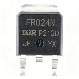
IRFR4105TRPBF - 55V 27A N-Channel HEXFET MOSFET | Infineon
MPN: IRFR4105TRPBF ✓ Active| Qty | Unit Price | Extended |
|---|---|---|
| 1 | $1.18 | $1.18 |
| 10 | $1.02 | $10.20 |
| 100 | $0.86 | $86.00 |
| 500 | $0.74 | $370.00 |
| 1,000 | $0.65 | $650.00 |
| 2,500 | $0.58 | $1,450.00 |
Drop-in alternatives for IRFR4105TRPBF — same package, pin-to-pin compatible. Different-package parts requiring PCB rework are excluded.
Quick Comparison Tool — Select alternative parts for side-by-side comparison:
IRFR4105Z
✅ Drop-In📋 Reference alternative (not in catalog)
IRFR3710ZTRPBF
✅ Drop-In✓ In Stock
$0.42 / Unit
View Datasheet →IRFR3410
✅ Drop-In📋 Reference alternative (not in catalog)
IRFR3411TRPBF
✅ Drop-In✓ In Stock
$0.55 / Unit
View Datasheet →IRFZ44NPBF
✅ Drop-In✓ In Stock
$0.65 / Unit
View Datasheet →IRFR4105TRPBF Maximum Ratings & Electrical Characteristics
| Transistor Type | N-Channel MOSFET |
| Technology | HEXFET (5th generation IR MOSFET) |
| Drain-Source Voltage (V_DS max) | 55 V |
| Continuous Drain Current (I_D at Tc) | 27 A |
| On-Resistance (R_DS(on) max at V_GS=10V) | 45 milliohm |
| Gate-Source Voltage (V_GS max) | 20 V |
| Total Gate Charge (Q_G) | 22.7 nC |
| Power Dissipation (P_D at Tc) | 68 W |
| Package | TO-252AA (DPAK) |
| Mounting Type | Surface Mount |
| Operating Temperature Range | -55C to +175C |
| RoHS Status | Compliant (lead-free, PBF suffix) |
| Packaging Type | Tape and Reel (TRPBF) |
IRFR4105TRPBF Pin Configuration
| Pin 1 | GATE — Gate control input (driven by gate driver or microcontroller PWM output) |
| Pin 2 | DRAIN — Drain terminal (also connected to the exposed rear tab for thermal dissipation) |
| Pin 3 | SOURCE — Source terminal (reference for gate drive and ground return path) |
Safe Operating Area (SOA)
Typical Applications
IRFR4105TRPBF is suitable for 7 applications: Automotive 12V/24V Load Switch, Synchronous Rectifier in DC-DC Converters, Brushed DC Motor Drive, Solenoid and Valve Driver, Reverse-Battery Protection Circuit, LED Lighting Driver Switch, Battery Management and Protection.
Automotive 12V/24V Load Switch
The IRFR4105TRPBF fits automotive 12V/24V load-switching applications because its 55V V_DS rating provides comfortable margin above the 24V nominal rail plus load-dump transients. Its 27A continuous drain current at Tc supports high-current accessories such as headlamp relays, fuel pumps, and HVAC blower motors. Placed between the battery rail and the load with a low-side topology, the MOSFET dissipates I^2 * 0.045 W during conduction - far lower than a mechanical relay's contact resistance. Designers should note that the part is not AEC-Q100 qualified, so it suits non-safety automotive subsystems where standard commercial-grade screening is acceptable. Tape-and-reel packaging (TRPBF) enables high-throughput surface-mount assembly on the body-controller PCB.
Recommended
Synchronous Rectifier in DC-DC Converters
As a synchronous rectifier on the low-side of a buck or boost converter, the IRFR4105TRPBF delivers 45 milliohm on-resistance that minimizes conduction loss in 12V-to-3.3V/5V step-down converters. Its 22.7 nC total gate charge allows switching frequencies up to several hundred kilohertz without excessive gate-drive loss, keeping efficiency above 90 percent in moderate-current designs. Placed across the inductor with its drain at switching node and source at ground, the device replaces a Schottky diode and eliminates the forward-voltage drop penalty. For best results, the gate should be driven by a dedicated MOSFET driver such as the IRS2104 to achieve rapid transitions and avoid shoot-through. The DPAK footprint also handles the 1-3W typical dissipation with a modest copper pour.
Recommended
Brushed DC Motor Drive
The IRFR4105TRPBF serves as the low-side switch in a brushed DC motor H-bridge or as a single-switch speed controller via PWM. Its 27A continuous drain current at Tc comfortably drives small-to-medium brushed motors in the 100W class, including windshield-wiper pumps, cooling fans, and power-tool triggers. PWM frequency in the 1-25 kHz range is well-supported by the 22.7 nC Q_G, and the 55V rating tolerates the inductive flyback that occurs when commutating a motor winding. A flyback diode across the motor or a snubber RC network is recommended to clamp V_DS below the 55V rating. The DPAK package's exposed tab mounts directly to a copper heatsink area on the PCB, providing the thermal dissipation path required under continuous stall-current conditions.
Recommended
Solenoid and Valve Driver
Solenoid and hydraulic-valve drivers benefit from the IRFR4105TRPBF's combination of low R_DS(on) and modest gate charge. Driving a 24V solenoid at PWM duty cycles up to 100 percent, the 45 milliohm on-resistance translates to minimal voltage drop across the switch, so the solenoid receives nearly the full rail voltage for maximum pull-in force. The 55V V_DS rating absorbs the inductive kick when the solenoid is de-energized, eliminating the need for an external flyback diode in low-energy applications. A freewheeling diode across the solenoid is still recommended best practice. The DPAK surface-mount package is well-suited to compact industrial-control PCBs.
Recommended
Reverse-Battery Protection Circuit
The IRFR4105TRPBF can be used as a high-side P-channel-replacement reverse-polarity protection switch by placing it in the ground return path with the load. Because the part is N-channel, drive circuitry is required to hold the gate above the source during normal operation. With 27A current handling and only 45 milliohm resistance, voltage drop is around 1.2V at full load - acceptable in 12V systems where the downstream regulator has dropout margin. The 55V breakdown easily survives the transient reverse-voltage events that occur when jump-starting a vehicle. A small Zener diode from gate to source protects the gate oxide during the brief reverse-polarity fault.
Recommended
LED Lighting Driver Switch
In PWM-dimmed LED driver circuits, the IRFR4105TRPBF operates as a low-side chopper switch controlling current through an LED string. With 27A capability and 45 milliohm R_DS(on), the MOSFET easily handles the 1-3A typical drive currents for automotive headlamp or architectural LED strings. Its fast switching and 22.7 nC Q_G support PWM dimming frequencies up to several kilohertz without visible flicker. The 55V V_DS rating tolerates the inductive transients from the LED load wiring. Mounted on a TO-252 DPAK with copper thermal relief, the part dissipates only milliwatts in steady-state operation, eliminating the need for a heatsink in most cases.
Recommended
Battery Management and Protection
In lithium-ion or lead-acid battery management systems, the IRFR4105TRPBF acts as a low-side disconnect switch or as the synchronous rectifier in a bidirectional buck-boost charger. Its 27A current rating handles the 5-15A typical charge/discharge currents of multi-cell battery packs, while the 55V breakdown withstands the stacked-cell voltage plus transients. The 45 milliohm on-resistance minimizes conduction loss during the long low-current float-charge phase, where total energy efficiency matters. For battery-protection applications requiring ultra-low quiescent drain, designers should add a small P-channel MOSFET in series with the gate drive. The DPAK package supports automated assembly on the battery-management PCB.
Recommended
Recommended Products Summary
Engineering reference data for IRFR4105TRPBF — comparison, design guidance, and compliance information.
Selection Guide
Comparison with Alternatives
| Parameter | This Product | IRFR4105Z | IRFR3710Z | IRFR3410 | IRFR3411 | IRFZ44NPBF |
|---|---|---|---|---|---|---|
| Brand | Infineon Technologies | Infineon Technologies | Infineon Technologies | Infineon Technologies | Infineon Technologies | Infineon Technologies |
| Package | TO-252AA (DPAK) | TO-252AA (DPAK) - same | TO-252AA (DPAK) - same | TO-252AA (DPAK) - same | TO-252AA (DPAK) - same | TO-252AA (DPAK) - same |
| Drain-Source Voltage (V_DS) | 55 V | 55 V | 55 V | 100 V | 60 V | 55 V |
| Continuous Drain Current (I_D) | 27 A | ~32 A | ~50 A | ~31 A | ~30 A | ~49 A |
| R_DS(on) max at V_GS=10V | 45 milliohm | ~25 milliohm | ~18 milliohm | ~39 milliohm | ~30 milliohm | ~17.5 milliohm |
| Total Gate Charge (Q_G) | 22.7 nC | [DATA_NEEDED] | [DATA_NEEDED] | [DATA_NEEDED] | [DATA_NEEDED] | [DATA_NEEDED] |
| Power Dissipation (P_D) | 68 W | ~68 W | ~100 W | ~68 W | ~68 W | ~94 W |
| RoHS / Lead-Free | Yes (PBF suffix) | Yes | Yes | Yes | Yes | Yes |
| Packaging Type | Tape and Reel | Tape and Reel | Tape and Reel | Tape and Reel | Tape and Reel | Tape and Reel |
Key Differentiators
- Lower R_DS(on) than predecessors at same V_DS (vs IRFR4105Z)
- Higher current capability in same package (vs IRFR3710Z)
- Voltage headroom upgrade (vs IRFR3410)
Design Notes
The TO-252 DPAK dissipates up to 68W only with the case held at 25C; in practice, the tab-to-ambient thermal resistance (theta_JA ~ 50C/W for a 1oz 1-square-inch copper pour) limits steady-state dissipation to roughly 2.5W at 125C junction. Estimated: at 5W dissipation the junction rises 250C above ambient, exceeding the 175C rating. Mount the DPAK tab onto a copper pour of at least 1 square inch, with thermal vias to inner copper planes for high-current designs above 3A continuous.
Keep the gate-drive loop physically small by placing the gate resistor and driver close to pin 1. The high-current loop from drain to source should not share copper with the gate loop, otherwise voltage spikes couple into the gate and cause ringing or shoot-through. Use a ground-return path directly beneath the source lead on an inner or top-layer copper pour. Stitch the input bypass capacitor return to the source pin, not to a distant ground point, to minimize parasitic inductance that exacerbates switching transients.
Do not exceed V_GS = 20V; even brief overvoltage on the gate oxide destroys the part. Add a 10V Zener from gate to source when the gate driver can produce transients above this rating, especially in half-bridge topologies with inductive kickback. For PWM motor-drive applications, verify that the peak V_DS during turn-off stays below 55V; if not, add a snubber or reduce PWM di/dt. Also confirm that V_GS(th) is below the logic-level drive voltage to ensure full enhancement at low duty cycles.
Compliance Information
PBF suffix confirms lead-free, RoHS-compliant terminal finish. Not AEC-Q100 qualified - for automotive safety applications use AEC-Q100-grade alternatives. Halogen-free status requires confirmation against latest Infineon declaration.