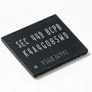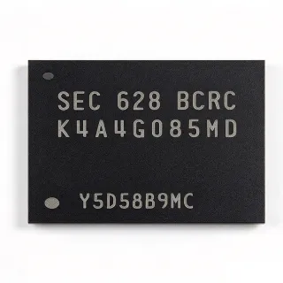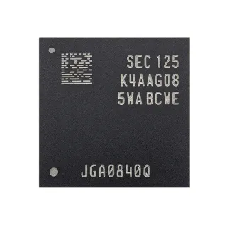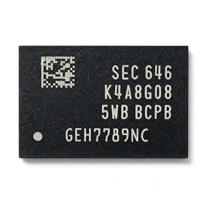
K4A8G085WB-BCPB - 8Gb DDR4 SDRAM 3200Mbps | Samsung
Teilenummer: K4A8G085WB-BCPB ✓ Aktiv| Menge | Stückpreis | Gesamt |
|---|---|---|
| 1 | $23.625 | $23,63 |
| 10 | $17.0625 | $170,63 |
| 100 | $15.0937 | $1.509,37 |
| 500 | $14.4375 | $7.218,75 |
| 1.000 | $13.7813 | $13.781,30 |
K4A8G085WB-BCPB Übersicht
DDR4 SDRAM (Double Data Rate 4 Synchronous Dynamic Random Access Memory) is a volatile memory technology that transfers data on both rising and falling edges of the clock, doubling the effective data rate. Within the memory hierarchy it sits below the memory controller and above storage, serving as main system memory. DDR4 succeeded DDR3 by lowering the core supply from 1.5V to 1.2V (up to 40% power reduction), increasing bank count from 8 to 16 via bank groups, and raising densities to 8Gb and beyond.
Key features of the K4A8G085WB-BCPB include the 3200 Mbps data rate (BC speed grade), CAS Latency 22, burst length 8, and 16 banks in 4 bank groups for improved parallelism. On-die termination (ODT) and dynamic ODT improve signal integrity, while temperature-compensated self-refresh (TCSR) reduces standby power.
The device is fabricated on Samsung's advanced DRAM process (B-die generation) and supports programmable read latency (RL) and write latency (WL). It runs from a 1.2V supply (nominal) with refresh intervals of 7.8 us up to 85C operating temperature. DLL-enabled mode operation ensures precise output timing across the speed range.
Typical applications include desktop and laptop DIMMs, embedded computing boards, industrial PCs, networking equipment, and test instrumentation requiring high bandwidth in a compact footprint.
When designing in this component, match memory controller timing parameters (CL22 at 3200 Mbps), place decoupling capacitors close to the power balls, and follow the length-matched fly-by routing of DDR4 for CK/CA/DQS nets.
This page adds distributor pricing data, drop-in alternatives within the same Samsung DDR4 x8 family, and cross-brand equivalents (SK Hynix, Micron, Nanya) not found in the manufacturer datasheet alone.
Drop-in-Alternativen für K4A8G085WB-BCPB – gleiches Gehäuse, Pin-kompatibel. Bauteile mit anderem Gehäuse, die eine PCB-Überarbeitung erfordern, sind ausgeschlossen.
Varianten dieser Serie
Modelle derselben Serie, die drop-in-kompatibel sind mit K4A8G085WB-BCPB (gleiche Bauform und Footprint) – abweichend in Package, Data Rate, Density, Operating Temperature, Organization.
Schnellvergleichstool – Wählen Sie Alternativbauteile für den Direktvergleich:
K4A8G085WB-BCRC
✓ Auf Lager
$6.8 / Stück
Datenblatt ansehen →K4A8G085WB-BITD
✓ Auf Lager
$3.8 / Stück
Datenblatt ansehen →K4A8G085WB-BIWE
✓ Auf Lager
$6.5 / Stück
Datenblatt ansehen →K4A8G085WC-BCTD
✓ Auf Lager
$50.85 / Stück
Datenblatt ansehen →K4A8G085WC-BIWE
✓ Auf Lager
$6.29 / Stück
Datenblatt ansehen →H5AN8G8NDJR
✓ Auf Lager
$24.5 / Stück
Datenblatt ansehen →MT40A1G8WE-075E
✓ Auf Lager
$11.9 / Stück
Datenblatt ansehen →K4A8G085WB-BCPB Grenzwerte & elektrische Eigenschaften
| Speichertyp | DDR4 SDRAM |
| Density | 8 Gbit |
| Speicherorganisation | 1G x 8 |
| Versorgungsspannung | 1.2 V (nominal) |
| Datenrate | 3200 Mbps (PC4-25600) |
| Speed Grade | BC |
| CAS Latency (CL) | 22 |
| Burst Length | 8 |
| Bank Architecture | 16 banks (4 bank groups) |
| Refresh Interval | 7.8 us (up to 85C) |
| Schnittstellentyp | SSTL-12 |
| Termination | ODT / dynamic ODT |
| Self-Refresh | Temperature-Compensated Self-Refresh (TCSR) |
| Gehäuse | 78-ball FBGA |
| Package Dimensions | 11 mm x 11 mm |
| Montageart | Surface Mount (BGA) |
| Operating Mode | DLL enabled |
| RoHS-Status | Compliant |
K4A8G085WB-BCPB Pin-Konfiguration
| Pin A1 | DQ0 — Data I/O bit 0 |
| Pin A2 | DQ1 — Data I/O bit 1 |
| Pin A3 | DQ2 — Data I/O bit 2 |
| Pin A7 | DQ3 — Data I/O bit 3 |
| Pin A8 | DQ4 — Data I/O bit 4 |
| Pin A9 | DQ5 — Data I/O bit 5 |
| Pin B7 | DQ6 — Data I/O bit 6 |
| Pin B8 | DQ7 — Data I/O bit 7 |
| Pin B9 | DM — Data input mask |
| Pin A4 | TDQS — Termination data strobe (tied to DQS in x8) |
| Pin B5 | TDQS# — Termination data strobe complement |
| Pin A5 | DQS — Data strobe |
| Pin B6 | DQS# — Data strobe complement |
| Pin C2 | A0 — Address input 0 |
| Pin C7 | A1 — Address input 1 |
| Pin C8 | A2 — Address input 2 |
| Pin D2 | A3 — Address input 3 |
| Pin D7 | A4 — Address input 4 |
| Pin D8 | A5 — Address input 5 |
| Pin E2 | A6 — Address input 6 |
| Pin E7 | A7 — Address input 7 |
| Pin E8 | A8 — Address input 8 |
| Pin F2 | A9 — Address input 9 |
| Pin F7 | A10 — Address input 10 / AP (auto precharge) |
| Pin F8 | A11 — Address input 11 |
| Pin G2 | A12 — Address input 12 / BC (burst chop) |
| Pin G7 | A13 — Address input 13 |
| Pin G8 | A14 — Address input 14 |
| Pin H2 | A15 — Address input 15 |
| Pin H7 | A16 — Address input 16 |
| Pin H8 | A17 — Address input 17 |
| Pin K2 | BA0 — Bank address 0 |
| Pin K7 | BA1 — Bank address 1 |
| Pin K8 | BG0 — Bank group address 0 |
| Pin L2 | BG1 — Bank group address 1 |
| Pin L7 | CK — Differential clock (positive) |
| Pin L8 | CK# — Differential clock (negative) |
| Pin M2 | CKE — Clock enable |
| Pin M7 | CS# — Chip select (active low) |
| Pin M8 | ODT — On-die termination control |
| Pin N2 | ACT# — Activation command input (active low) |
| Pin N7 | RST# — Reset (active low, pulldown) |
| Pin N8 | PAR — Command/address parity input |
| Pin P2 | ALERT# — Alert output (open drain, pulldown) |
| Pin G1 | VDDQ — DQ power supply (1.2V) |
| Pin H1 | VDDQ — DQ power supply (1.2V) |
| Pin J1 | VDDQ — DQ power supply (1.2V) |
| Pin K1 | VDDQ — DQ power supply (1.2V) |
| Pin G9 | VSSQ — DQ ground |
| Pin H9 | VSSQ — DQ ground |
| Pin J9 | VSSQ — DQ ground |
| Pin K9 | VSSQ — DQ ground |
| Pin D1 | VDD — Core power supply (1.2V) |
| Pin E1 | VDD — Core power supply (1.2V) |
| Pin F1 | VDD — Core power supply (1.2V) |
| Pin D9 | VSS — Core ground |
| Pin E9 | VSS — Core ground |
| Pin F9 | VSS — Core ground |
| Pin M1 | VDD — Core power supply (1.2V) |
| Pin N1 | VDD — Core power supply (1.2V) |
| Pin M9 | VSS — Core ground |
| Pin N9 | VSS — Core ground |
| Pin C1 | VPP — DRAM activation power supply (2.5V) |
| Pin C3 | VPP — DRAM activation power supply (2.5V) |
| Pin C9 | VPP — DRAM activation power supply (2.5V) |
| Pin B1 | VSS — Ground |
| Pin B2 | VSS — Ground |
| Pin A6 | NC — Not connected (per datasheet) |
| Pin B3 | NC — Not connected (per datasheet) |
| Pin B4 | NC — Not connected (per datasheet) |
| Pin J2 | NC — Not connected (per datasheet) |
| Pin J7 | NC — Not connected (per datasheet) |
| Pin J8 | NC — Not connected (per datasheet) |
| Pin L1 | NC — Not connected (per datasheet) |
| Pin L9 | NC — Not connected (per datasheet) |
| Pin P1 | NC — Not connected (per datasheet) |
| Pin P7 | NC — Not connected (per datasheet) |
| Pin P8 | NC — Not connected (per datasheet) |
| Pin P9 | NC — Not connected (per datasheet) |
Typische Anwendungen
K4A8G085WB-BCPB ist geeignet für 6 Anwendungs: Desktop and Laptop Main Memory, Embedded Computing and Industrial PCs, Networking and Communications Equipment, Server and Data Center Memory Modules, Test and Measurement Instrumentation, Medical Imaging and Diagnostic Devices.
Desktop and Laptop Main Memory
The K4A8G085WB-BCPB is a core building block for PC4-25600 UDIMM and SO-DIMM modules used in desktop and laptop computers. Its 8Gb density in a 1G x 8 organization allows eight devices to populate a 64-bit channel with ECC on x8 lanes, while the 3200 Mbps data rate at CL22 matches mainstream DDR4 memory controller support. The 1.2V rail reduces module power versus DDR3, and dynamic ODT helps maintain signal integrity across multi-rank topologies. For module designers, the 11mm x 11mm FBGA-78 footprint aligns with standard DIMM land patterns, and TCSR trims standby power in mobile sleep states, extending battery life in portable systems.
Empfohlen
Embedded Computing and Industrial PCs
Industrial PCs, gateways, and embedded x86/ARM boards use the K4A8G085WB-BCPB soldered down for main memory, gaining 8Gb per device without SO-DIMM sockets that suffer from vibration. The 1.2V DDR4 interface reduces system heat in sealed fanless enclosures, while the 3200 Mbps grade matches common chipsets such as Intel Atom and AMD Ryzen Embedded families. Designers should place per-ball decoupling capacitors and length-match fly-by control nets. For extended-temperature deployments, consider the industrial-coded -BITD sibling, which shares the same footprint, keeping the PCB unchanged while improving the operating envelope.
Empfohlen
Networking and Communications Equipment
Switches, routers, and network appliances rely on the K4A8G085WB-BCPB for packet buffering and deep-flow tables, where the 16-bank, 4-bank-group architecture improves random-access parallelism and effective bandwidth. The x8 organization supports ECC scrubbing essential for long-uptime infrastructure, and 3200 Mbps operation keeps memory from bottlenecking multi-gigabit data paths. The 78-ball FBGA packages densely on control-line cards. Thermal design should account for continuous full-bandwidth traffic; use air flow plus thermal vias under the package, and enable ODT per the controller's calibration routine to hold margins across temperature.
Empfohlen
Server and Data Center Memory Modules
In RDIMM and ECC UDIMM builds, the K4A8G085WB-BCPB provides the x8 width required for single-device data correction (SDDC) on Intel and AMD server platforms. The BC-grade CL22 timing at DDR4-3200 aligns with standard server memory profiles, and the B-die silicon is well characterized for high reliability. Registered modules buffer command/address to scale to 16+ DIMMs per channel population. Designers stacking dual-rank DIMMs should verify CK/CA loading and drive-strength settings, and use the manufacturer datasheet refresh tables (7.8 us up to 85C) when configuring the memory controller's refresh rate in thermally constrained chassis.
Empfohlen
Test and Measurement Instrumentation
Oscilloscopes, logic analyzers, and arbitrary waveform generators need large, fast capture buffers, making the K4A8G085WB-BCPB a fit with its 3200 Mbps streaming capability and 8Gb per device. Multiple devices in 64-bit or 72-bit (ECC) arrays deliver the sustained write bandwidth needed for real-time acquisition without sample loss. The 1.2V interface reduces noise coupling into sensitive analog front ends versus older 1.5V DDR3 designs. Instrument designers should implement write-leveling and read-training firmware during production calibration, since FBGA soldered-down DRAM in compact boards demands precise per-trace timing closure for full-speed operation.
Empfohlen
Medical Imaging and Diagnostic Devices
Ultrasound, digital radiography, and lab analyzers accumulate large frame buffers that the K4A8G085WB-BCPB serves with 8Gb density and 3200 Mbps bandwidth, enabling real-time image pipelines at 1.2V power levels suited to patient-adjacent equipment. The soldered FBGA-78 package avoids connector reliability issues in mobile carts, and temperature-compensated self-refresh keeps standby draw low between scans. Designers should verify refresh timing against the datasheet operating window and use ECC-capable x8 organization to protect diagnostic data integrity. Add ground-plane shielding between DRAM and analog capture front ends to preserve low-noise imaging performance.
Empfohlen
Zusammenfassung der empfohlenen Produkte
Technische Referenzdaten für K4A8G085WB-BCPB – Vergleich, Designhinweise und Compliance-Informationen.
Auswahlhilfe
Vergleich mit Alternativen
| Parameter | Dieses Produkt | K4A8G085WB-BCRC | K4A8G085WC-BCTD | H5AN8G8NDJR | MT40A1G8WE-075E |
|---|---|---|---|---|---|
| Package | 78-ball FBGA | 78-ball FBGA - same | 78-ball FBGA - same | 78-ball FBGA - same (JEDEC) | 78-ball FBGA - same (JEDEC) |
| Brand | Samsung Electronics | Samsung Electronics | Samsung Electronics | SK Hynix | Micron |
| Density | 8 Gbit | 8 Gbit | 8 Gbit | 8 Gbit | 8 Gbit |
| Organization | 1G x 8 | 1G x 8 | 1G x 8 | 1G x 8 | 1G x 8 |
| Data Rate | 3200 Mbps | 2666 Mbps (RC grade) | 2666 Mbps | 2666 Mbps (JR grade) | 1866 Mbps |
| Supply Voltage | 1.2 V | 1.2 V | 1.2 V | 1.2 V | 1.2 V |
| CAS Latency | 22 | 19 (at grade rate) | 19 | 19 | 15 |
| Bank Architecture | 16 banks / 4 bank groups | 16 banks / 4 bank groups | 16 banks / 4 bank groups | 16 banks / 4 bank groups | 16 banks / 4 bank groups |
Wichtigste Unterscheidungsmerkmale
- Full DDR4-3200 (BC grade) speed support (vs. K4A8G085WB-BCRC)
- High-volume B-die supply base (vs. MT40A1G8WE-075E)
- ECC-ready x8 organization with TDQS (vs. K4A8G165WC-BCWE)
Designhinweise
Route DDR4 using the standard fly-by topology for CK, address, and command nets with on-die termination enabled; keep DQS/DQ length-matched within the controller's specified skew window. Provide at least one 0.1uF decoupling capacitor per VDD/VDDQ ball pair placed within 2mm of the package, plus bulk capacitance at the voltage regulator module. The 78-ball FBGA footprint is JEDEC-standard, so land patterns interchange freely across Samsung, SK Hynix, and Micron x8 DDR4 devices.
The K4A8G085WB-BCPB requires two rails: 1.2V VDD/VDDQ and 2.5V VPP for word-line activation. Size the VPP rail for low average current but be aware activation peaks; do not omit VPP decoupling, as VPP droop causes cell instability errors. Estimated: total active power at DDR4-3200 per device is typically a few hundred milliwatts, dominated by I/O switching; verify against the datasheet IDD figures for your specific traffic pattern.
Configure the memory controller to the BC speed grade timing tables (CL22 at 3200 Mbps) before bring-up; running faster grade timings on slower-coded parts causes intermittent bit errors. Perform write-leveling, read training, and DQS gate calibration at every boot and at temperature extremes. When substituting the -BCRC or -BITD siblings, re-verify SPD data and controller settings - the package is identical but speed bins and temperature coding differ.
Compliance-Informationen
RoHS compliance per standard Samsung DRAM product data; REACH and halogen-free status not stated in provided data.